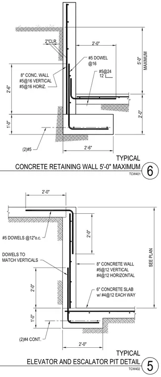
Two typical cast-in-place concrete details feature an eight-inch concrete retaining wall with a five-foot maximum height and an elevator and escalator pit assembly. The retaining wall rests on a continuous concrete footing measuring two feet six inches wide and two feet deep, reinforced with two continuous number five bars and number five vertical dowels spaced at sixteen inches on center. The wall itself incorporates number five vertical and horizontal reinforcing bars at sixteen-inch intervals with a two-inch clear cover. The elevator and escalator pit detail includes an eight-inch concrete wall with number five vertical bars at twelve-inch spacing and number four horizontal bars at twelve-inch spacing, tying into a six-inch concrete slab reinforced with number four bars each way and supported by two continuous number four bars in the footing.
TCW402 5 SEE PLAN 2'-0" 2'-0" #5 DOWELS @12"o.c. 8" CONCRETE WALL #5@12 VERTICAL #4@12 HORIZONTAL DOWELS TO MATCH VERTICALS 6" CONCRETE SLAB w/ #4@12 EACH WAY (2)#4 CONT. 2'-0" 1'-0" 2'-0" 1'-0" 2'-6" 2'-6" 5'-0" MAXIMUM TYPICAL CONCRETE RETAINING WALL 5'-0" MAXIMUM 6 8" CONC. WALL #5@16 VERTICAL #5@16 HORIZ. 2"CLR. 2'-0" #5 DOWEL @16 #5@24 12 (2)#5 2'-0" TCW401 TYPICAL ELEVATOR AND ESCALATOR PIT DETAIL
Members view this detail in full resolution, download the CAD files (SVG, PDF), and can adapt it in the built-in CAD editor — export DXF, DWG, or PDF.
Start membership