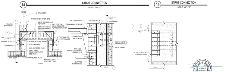
A structural strut connection ties into a precast concrete wall panel utilizing embedded steel plates and reinforcing. The assembly features a 12 inch by 6 inch by 3/8 inch plate P-6 embed connected to framing and a 1/2 inch by 12 inch by 3-0 inch plate with a quarter inch fillet weld. Vertical panel reinforcing, custom mesh, and surface reinforcing are integrated into the concrete panel. EPS insulation is removed locally to provide 1 inch clearance, supplemented by three number 4 U-bars and six number 5 by 48 inch long bars. Additional components include number 6 vertical bars each face in the return leg and 10 inch by 4 inch by 3/8 inch typical plates.
15 STRUT CONNECTION SCALE: 3/4"=1'-0" 14 STRUT CONNECTION SCALE: 3/4"=1'-0" GRID PLAN VIEW A - B - 10x4x3/8" PLATE TYP 1/4 P-6 EMBED CUSTOM MESH CUT VERTICAL MESH TO PLACE PLATE CONNECTION CL OF GIRDER VERT. PANEL REINFORCING, TYP. SEE PLAN 1' #6 VERT. BAR E.F. (4) IN RETURN LEG A SECTION 2" 1/4 PL 1/2"x12"x3'-0" CONNECTION BY OTHERS FRAMING BY OTHERS 3" 3" 6" B SECTION 6" 6" 6" 6" PL 3/4"x"t"x3'-0" W' (6) #5X48" LONG REMOVE EPS TO PROVIDE 1" CLR TIPS PANEL PER PLAN SURFACE REINFORCING 5" DBA EACH ROW SEE ELEVATION VERT. REINFORCING PER PLAN #4 U-BARS SEE PLAN STD. HOOK FRAMING BY OTHERS CONNECTION BY OTHERS 12"x6"x3/8" PLATE P-6 EMBED 6" 6" 8" 8" 8" TIPS MESH CONTINUED BEHIND CONNECTION REMOVE EPS TO PROVIDE 1" CLR. (3) #4 U-BARS SURFACE REINFORCING 1/4 6/30/2023
Members view this detail in full resolution, download the CAD files (SVG, PDF), and can adapt it in the built-in CAD editor — export DXF, DWG, or PDF.
Start membership