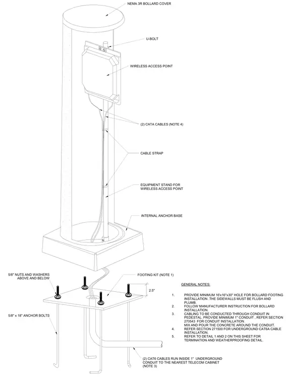
This installation detail shows a wireless access point housed inside a NEMA 3R bollard cover secured to an internal anchor base and equipment stand. The assembly is anchored to a concrete footing using four 5/8-inch by 18-inch anchor bolts with 5/8-inch nuts and washers positioned above and below the footing kit. Two Cat6 cables run inside a 1-inch underground conduit from the pedestal to the nearest telecom cabinet, secured along the internal stand with cable straps. The bollard footing requires a minimum 16-inch by 16-inch by 30-inch hole with flush, plumb sidewalls cast around the incoming conduit.
GROUNDING CONDUCTOR ATTACHED 1. PROVIDE MINIMUM 16'x16''x30'' HOLE FOR BOLLARD FOOTING INSTALLATION .THE SIDEWALLS MUST BE FLUSH AND PLUMB. 2. FOLLOW MANUFACTURER INSTRUCTION FOR BOLLARD INSTALLATION. 3. CABLING TO BE CONDUCTED THROUGH CONDUIT IN PEDESTAL. PROVIDE MINIMUM 1'' CONDUIT , REFER SECTION 270543 FOR CONDUIT INSTALLATION. MIX AND POUR THE CONCRETE AROUND THE CONDUIT. 4. REFER SECTION 271500 FOR UNDERGROUND CAT6A CABLE INSTALLATION. 5. REFER TO DETAIL 1 AND 2 ON THIS SHEET FOR TERMINATION AND WEATHERPROOFING DETAIL. GENERAL NOTES: INTERNAL ANCHOR BASE EQUIPMENT STAND FOR WIRELESS ACCESS POINT NEMA 3R BOLLARD COVER WIRELESS ACCESS POINT 5/8'' NUTS AND WASHERS ABOVE AND BELOW U-BOLT 2.5'' 5/8'' x 18'' ANCHOR BOLTS FOOTING KIT (NOTE 1) (2) CATA CABLES (NOTE 4) (2) CAT6 CABLES RUN INSIDE 1'' UNDERGROUND CONDUIT TO THE NEAREST TELECOM CABINET (NOTE 3) CABLE STRAP
Members view this detail in full resolution, download the CAD files (SVG, PDF), and can adapt it in the built-in CAD editor — export DXF, DWG, or PDF.
Start membership