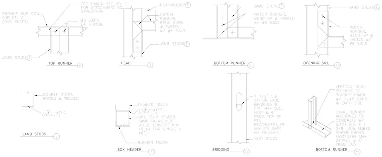
Metal stud partition framing details illustrate the connection and assembly methods for cold-formed steel framing components. The top track utilizes a slip connection anchored to the concrete structure with 0.177-inch diameter by 1-3/8-inch minimum embedment power-driven fasteners spaced at a maximum of 24 inches on center and 6 inches from the end. Vertical studs secure to the runner track with one number 8 sheet metal screw at each flange on each side. The head and sill details show jamb studs engaging notched runner tracks bent and fastened with number 8 sheet metal screws. Box headers consist of double studs housed within runner tracks with 1/8-inch welds spaced at 1-1/2 inches typical. Stud bridging incorporates 1-1/2-inch cold-rolled channels spaced at a maximum of 5 feet on center vertically and 6 inches from the top of the partition regardless of applied sheathing or finishes.
(THIS SHEET) TOP TRACK SEE DTL 2 STRUCTURE FOR DTL 2 FOR ATTACHMENT TO PROVIDE SLIP CON. CONT. RUNNER ANCHORED TO CONCRETE W/ 0.177 DIA. X 1 3/8" MIN. EMBED POWER DRIVEN FASTENERS MAX 24"O.C. & 6" FROM END VERTICAL STUD SECURED TO RUNNER TRACK W/ 1-#8 S.M.S. @ EACH SIDE H 1 1/2" C.R. CH OR STUD BRIDGING @ 5'0" MAX O.C. VERT & 6" FROM TOP OF PTN REGARDLESS OF APPLIED SHTG OR FINISHES VERT STUDS G 1-12 1/8 RUNNER TRACK DBL STUD HEADER, SAME GA AS VERT STUDS (EXCEPT MIN 18 GA FOR OPNGS > 48") RUNNER TRACK TYP. F 1-12 TYP. BOXED & WELDED DOUBLE STUDS 1/8 E E JAMB STUDS NOTCH RUNNER, BEND UP & FASTEN w/ #8 S.M.S D E JAMB STUDS NOTCH RUNNER, BEND UP & FASTEN w/ #8 S.M.S C F E B JAMB STUDS BOX HEADER NOTCH RUNNER, BEND DOWN & FASTEN w/ #8 S.M.S #8 S.M.S EA. FLANGE, TYP E JAMB STUDS A BOTTOM RUNNER BRIDGING BOX HEADER JAMB STUDS OPENING SILL BOTTOM RUNNER HEAD TOP RUNNER
Members view this detail in full resolution, download the CAD files (SVG, PDF), and can adapt it in the built-in CAD editor — export DXF, DWG, or PDF.
Start membership