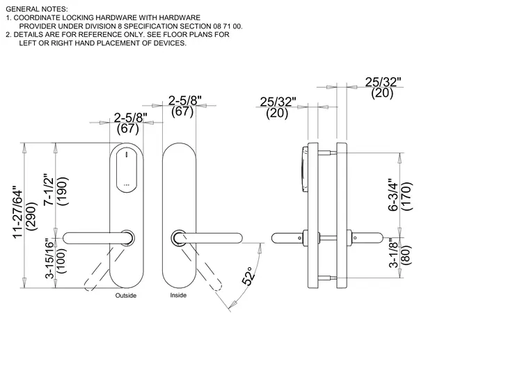
An exterior and interior dimensioned profile of a wireless access control card reader assembly. The unit has an overall height of 11-27/64 inches (290 mm) with a lever handle located 3-15/16 inches (100 mm) from the bottom and a 7-1/2 inch (190 mm) spacing to the upper reader face. The overall depth includes 25/32 inch (20 mm) projections on both the inside and outside faces. Lever rotation is detailed with a 52-degree operating range. General notes coordinate locking hardware requirements with Division 8 specification section 08 71 00 and reference floor plans for hand placement.
2-5/8" (67) Outside Inside 2-5/8" (67) 25/32" (20) 25/32" (20) GENERAL NOTES: 1. COORDINATE LOCKING HARDWARE WITH HARDWARE PROVIDER UNDER DIVISION 8 SPECIFICATION SECTION 08 71 00. 2. DETAILS ARE FOR REFERENCE ONLY. SEE FLOOR PLANS FOR LEFT OR RIGHT HAND PLACEMENT OF DEVICES. 11-27/64" (290) 3-15/16" (100) 7-1/2" (190) 3-1/8" (80) 6-3/4" (170) 52°
Members view this detail in full resolution, download the CAD files (SVG, PDF), and can adapt it in the built-in CAD editor — export DXF, DWG, or PDF.
Start membership