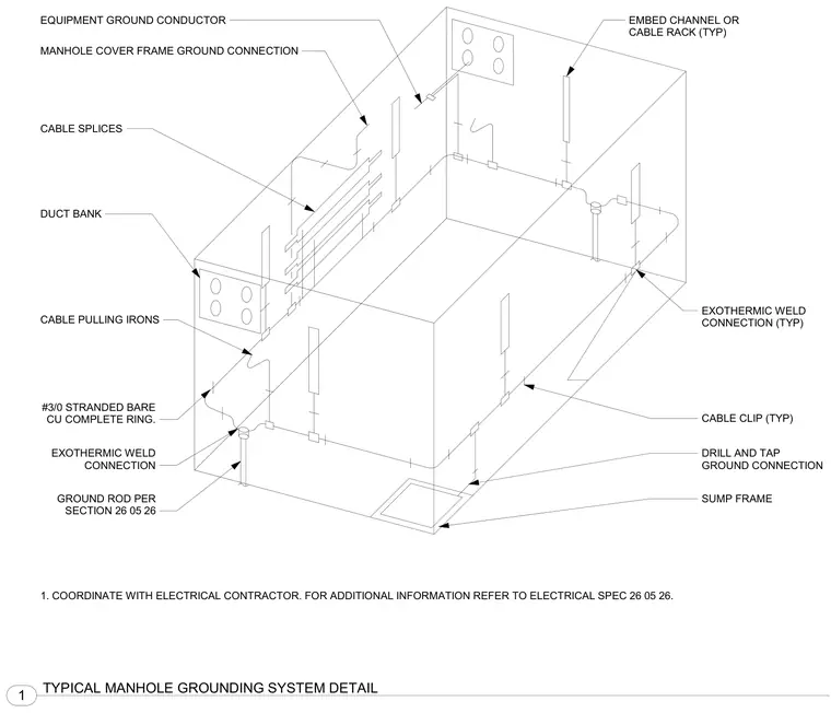
A complete underground electrical manhole grounding ring consists of a number three-zero stranded bare copper conductor running continuously around the interior perimeter. Ground rods tie into the ring via exothermic weld connections, with additional exothermic welds securing equipment ground conductors, cable pulling irons, and sump frames. Embed channels or cable racks attach along the walls and tie into the ground network with cable clips and drill and tap connections. The manhole cover frame receives a dedicated ground connection linking back to the main ring. All work coordinates with the electrical contractor per section 26 05 26.
EMBED CHANNEL OR CABLE RACK (TYP) EQUIPMENT GROUND CONDUCTOR MANHOLE COVER FRAME GROUND CONNECTION CABLE SPLICES DUCT BANK CABLE PULLING IRONS #3/0 STRANDED BARE CU COMPLETE RING. EXOTHERMIC WELD CONNECTION GROUND ROD PER SECTION 26 05 26 SUMP FRAME EXOTHERMIC WELD CONNECTION (TYP) CABLE CLIP (TYP) DRILL AND TAP GROUND CONNECTION 1. COORDINATE WITH ELECTRICAL CONTRACTOR. FOR ADDITIONAL INFORMATION REFER TO ELECTRICAL SPEC 26 05 26. 1 TYPICAL MANHOLE GROUNDING SYSTEM DETAIL
Members view this detail in full resolution, download the CAD files (SVG, PDF), and can adapt it in the built-in CAD editor — export DXF, DWG, or PDF.
Start membership