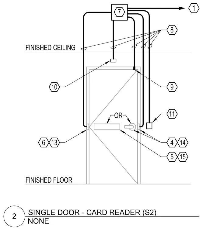
A single door access control rough-in diagram showing conduit routing between a junction box above the finished ceiling and various door hardware components. Low-voltage cabling extends to a card reader, door contact, request-to-exit device, and electronic lock or electric strike. Reference callouts identify connections for door positioning switches, locking hardware, and control panels relative to the finished floor and finished ceiling lines.
1 OR 13 4 5 7 8 9 10 FINISHED FLOOR FINISHED CEILING 11 6 14 15 NONE 2 SINGLE DOOR - CARD READER (S2)
Members view this detail in full resolution, download the CAD files (SVG, PDF), and can adapt it in the built-in CAD editor — export DXF, DWG, or PDF.
Start membership