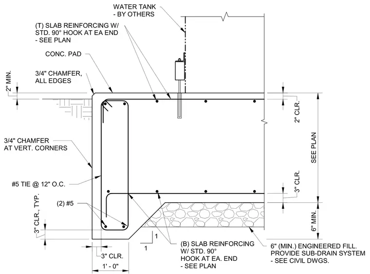
A reinforced concrete pad rests on a minimum of six inches of engineered fill over a sub-drain system. The perimeter features a thickened edge with a one-foot width, containing two number five horizontal bars and number five ties spaced at twelve inches on center. Both top and bottom slab reinforcing consist of bars with standard ninety-degree hooks at each end, sized per plan. Concrete clear cover is maintained at two inches minimum at the top and three inches at the bottom and vertical edges. All concrete edges and vertical corners include three-quarter-inch chamfers. The water tank, provided by others, is anchored to the top of the concrete pad.
2" MIN. 3/4" CHAMFER, ALL EDGES CONC. PAD 2" CLR. 3" CLR. 6" MIN. SEE PLAN 3" CLR., TYP. 3" CLR. 1' - 0" 3/4" CHAMFER AT VERT. CORNERS (2) #5 1 1 (B) SLAB REINFORCING W/ STD. 90° HOOK AT EA. END - SEE PLAN 6" (MIN.) ENGINEERED FILL. PROVIDE SUB-DRAIN SYSTEM - SEE CIVIL DWGS. #5 TIE @ 12" O.C. WATER TANK - BY OTHERS (T) SLAB REINFORCING W/ STD. 90° HOOK AT EA END - SEE PLAN
Members view this detail in full resolution, download the CAD files (SVG, PDF), and can adapt it in the built-in CAD editor — export DXF, DWG, or PDF.
Start membership