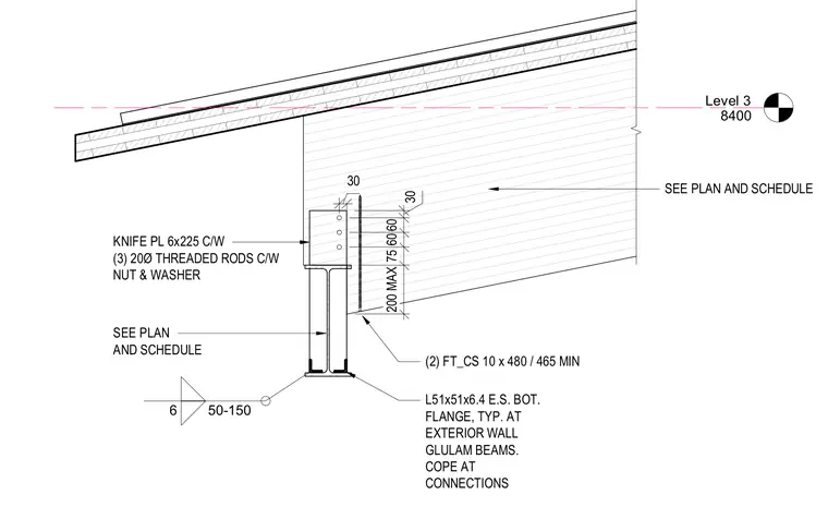
The glulam beam connects to the supporting member using a 6x225 knife plate secured by three 20 diameter threaded rods complete with nuts and washers. An angle member L51x51x6.4 is provided each side at the bottom flange, typical at exterior wall glulam beams with a cope at connections. Additional framing components include two FT_CS 10 x 480 / 465 minimum elements. Layout and member sizing are coordinated per the structural plan and schedule.
Level 3 8400 30 30 60 60 75 200 MAX L51x51x6.4 E.S. BOT. FLANGE, TYP. AT EXTERIOR WALL GLULAM BEAMS. COPE AT CONNECTIONS KNIFE PL 6x225 C/W (3) 20Ø THREADED RODS C/W NUT & WASHER SEE PLAN AND SCHEDULE SEE PLAN AND SCHEDULE 6 50-150 (2) FT_CS 10 x 480 / 465 MIN
Members view this detail in full resolution, download the CAD files (SVG, PDF), and can adapt it in the built-in CAD editor — export DXF, DWG, or PDF.
Start membership