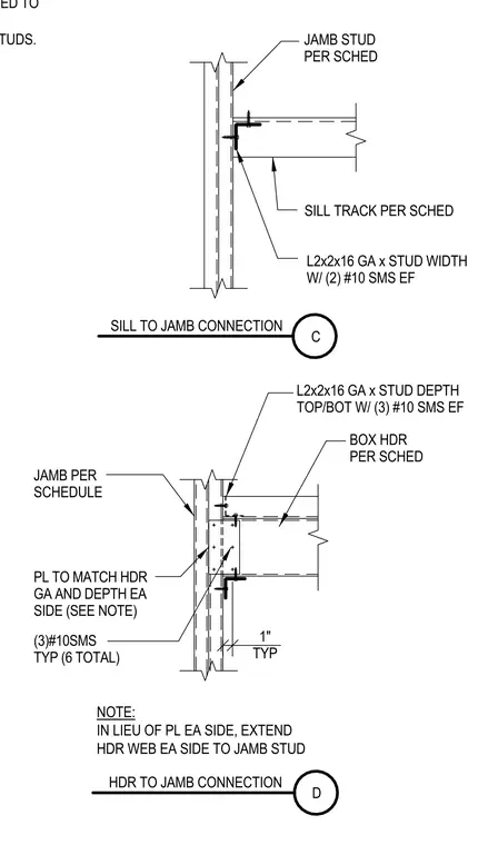
The sill track connects to the jamb stud per schedule using an L2x2x16 gauge angle sized to the stud width secured with two number ten sheet metal screws each flange. The box header connects to the jamb using a plate matching the header gauge and depth on each side secured with three number ten sheet metal screws typically for a total of six, or alternatively by extending the header web directly to the jamb stud. Top and bottom angles of L2x2x16 gauge sized to the stud depth fasten the box header with three number ten sheet metal screws each flange. Bridging is provided at forty-eight inches on center or per manufacturer requirements where gypsum board is not applied.
1" TYP JAMB STUD PER SCHED SILL TRACK PER SCHED L2x2x16 GA x STUD WIDTH W/ (2) #10 SMS EF JAMB PER SCHEDULE PL TO MATCH HDR GA AND DEPTH EA SIDE (SEE NOTE) (3)#10SMS TYP (6 TOTAL) BOX HDR PER SCHED L2x2x16 GA x STUD DEPTH TOP/BOT W/ (3) #10 SMS EF NOTE: IN LIEU OF PL EA SIDE, EXTEND HDR WEB EA SIDE TO JAMB STUD SILL TO JAMB CONNECTION C HDR TO JAMB CONNECTION D PROVIDE BRIDGING @ 48"OC OR PER MFR WHERE GYPSUM BOARD IS NOT APPLIED TO SEE ARCHITECTURAL DRAWINGS FOR SIZE, LOCATION AND EXTENT OF METAL STUDS.
Members view this detail in full resolution, download the CAD files (SVG, PDF), and can adapt it in the built-in CAD editor — export DXF, DWG, or PDF.
Start membership