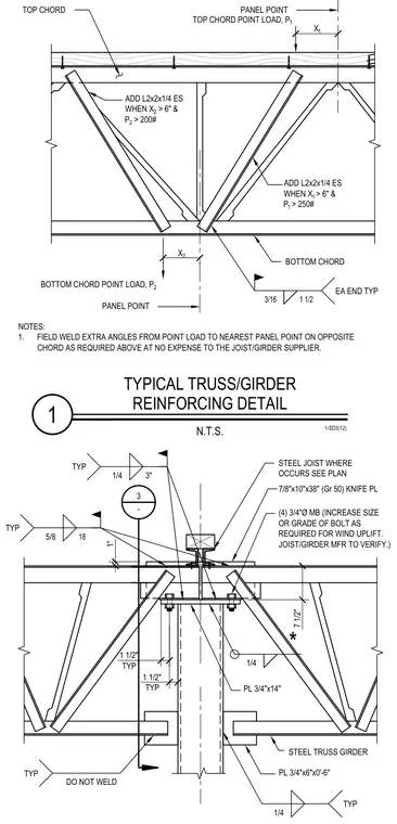
A steel truss girder is supported by a column with reinforcing plates and knife plate connections. The assembly includes a 7/8 inch by 10 inch by 38 inch Grade 50 knife plate, a 3/4 inch by 14 inch plate, and four 3/4 inch diameter machine bolts configured for wind uplift verification by the manufacturer. Additional angle reinforcements such as L2x2x1/4 are specified for top and bottom chords when point loads and offset distances exceed specified thresholds. Fillet welds of 3/16 inch and 1/4 inch are noted throughout the connection, with specific regions left unwelded to the girder as indicated.
1 TYPICAL TRUSS/GIRDER REINFORCING DETAIL N.T.S. 1-SD3(12) PL 3/4"x6"x0'-6" DO NOT WELD PL 3/4"x14" 7/8"x10"x38" (Gr 50) KNIFE PL STEEL JOIST WHERE OCCURS SEE PLAN 1 1/2" TYP 1" 7 1/2" 3 - 1/4 1/4 TYP TYP 5/8 18 TYP STEEL TRUSS GIRDER * (4) 3/4"Ø MB (INCREASE SIZE OR GRADE OF BOLT AS REQUIRED FOR WIND UPLIFT. JOIST/GIRDER MFR TO VERIFY.) 1/4 3" TYP 1 1/2" TYP NOTES: 1. FIELD WELD EXTRA ANGLES FROM POINT LOAD TO NEAREST PANEL POINT ON OPPOSITE CHORD AS REQUIRED ABOVE AT NO EXPENSE TO THE JOIST/GIRDER SUPPLIER. PANEL POINT BOTTOM CHORD POINT LOAD, P 2 TOP CHORD POINT LOAD, P 1 TOP CHORD BOTTOM CHORD X 1 ADD L2x2x1/4 ES WHEN X 1 > 6" & P 1 > 250# ADD L2x2x1/4 ES WHEN X 2 > 6" & P 2 > 200# PANEL POINT X 2 3/16 1 1/2 EA END TYP
Members view this detail in full resolution, download the CAD files (SVG, PDF), and can adapt it in the built-in CAD editor — export DXF, DWG, or PDF.
Start membership