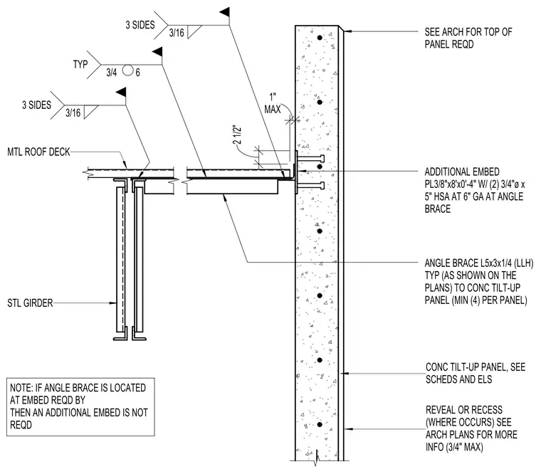
A concrete tilt-up panel connects to a steel roof framing system featuring a steel girder and metal roof deck. An angle brace measuring L5x3x1/4 connects the tilt-up panel with a minimum of four per panel, welded with three-sixteenth inch welds on three sides. An additional embed plate measuring three-eighths by eight inches by four inches features two three-quarter inch diameter by five-inch head stud anchors at a six-inch gauge at the angle brace location. The metal roof deck bears near the panel with a one-inch maximum gap and a two-and-a-half-inch maximum dimension shown for the connection assembly. A note indicates that if the angle brace is located at the embed required by the design, an additional embed is not required.
SEE ARCH FOR TOP OF PANEL REQD ADDITIONAL EMBED PL3/8"x8'x0'-4" W/ (2) 3/4"ø x 5" HSA AT 6" GA AT ANGLE BRACE 3 SIDES 3/16 NOTE: IF ANGLE BRACE IS LOCATED AT EMBED REQD BY THEN AN ADDITIONAL EMBED IS NOT REQD TYP 3/4 6 ANGLE BRACE L5x3x1/4 (LLH) TYP (AS SHOWN ON THE PLANS) TO CONC TILT-UP PANEL (MIN (4) PER PANEL) 3 SIDES 3/16 STL GIRDER MTL ROOF DECK REVEAL OR RECESS (WHERE OCCURS) SEE ARCH PLANS FOR MORE INFO (3/4" MAX) CONC TILT-UP PANEL, SEE SCHEDS AND ELS 2 1/2" MAX 1"
Members view this detail in full resolution, download the CAD files (SVG, PDF), and can adapt it in the built-in CAD editor — export DXF, DWG, or PDF.
Start membership