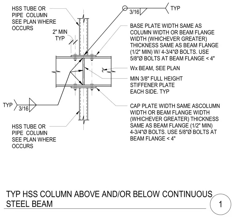
A continuous steel beam passes between an upper and lower hollow structural section tube or pipe column located as sized per plan. The upper column connects to the top flange of the beam using a base plate matching the column or beam flange width, whichever is greater, with a minimum thickness of one-half inch and secured by four three-quarter inch diameter bolts, switching to five-eighth inch diameter bolts when the beam flange is under four inches. The lower column connects similarly to the bottom flange of the beam using a cap plate of matching dimensions and four bolts. Inside the hollow structural section, minimum three-eighth inch full-height stiffener plates are welded to each side using three-sixteenth inch typical fillet welds.
CAP PLATE WIDTH SAME ASCOLUMN WIDTH OR BEAM FLANGE WIDTH (WHICHEVER GREATER) THICKNESS SAME AS BEAM FLANGE (1/2" MIN) 4-3/4"Ø BOLTS. USE 5/8"Ø BOLTS AT BEAM FLANGE < 4" HSS TUBE OR PIPE COLUMN SEE PLAN WHERE OCCURS MIN 3/8" FULL HEIGHT STIFFENER PLATE EACH SIDE. TYP BASE PLATE WIDTH SAME AS COLUMN WIDTH OR BEAM FLANGE WIDTH (WHICHEVER GREATER) THICKNESS SAME AS BEAM FLANGE (1/2" MIN) W/ 4-3/4"Ø BOLTS. USE 5/8"Ø BOLTS AT BEAM FLANGE < 4" 3/16 TYP TYP 2" MIN 3/16 TYP HSS TUBE OR PIPE COLUMN SEE PLAN WHERE OCCURS Wx BEAM, SEE PLAN TYP HSS COLUMN ABOVE AND/OR BELOW CONTINUOUS STEEL BEAM 1
Members view this detail in full resolution, download the CAD files (SVG, PDF), and can adapt it in the built-in CAD editor — export DXF, DWG, or PDF.
Start membership