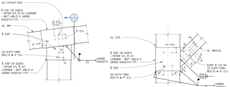
Glulam beam and brace connections feature mitered steel plates on three sides joined with butt welds and ground smooth. The glulam beam connects via a top plate fastened with six quarter-inch diameter by five-inch SDS screws and two three-quarter-inch through bolts spaced at four inches on center. The glulam brace frames into a glued column using a half-inch kerf plate secured by two five-eighths-inch through bolts at four inches on center, along with four three-quarter-inch through bolts on the main connection plate.
GL. BM 6 3/8" (3) SIDES - MITER STL 6 AT CORNER - BUTT WELD & GRIND SMOOTH TYP. (6) 1/4" 4x5" SDS (2) 3/4" 4 THRU BOLTS @ 4" O.C. 3" O.C. TYP. 3" O.C. 5 S-110 5██████████ 5██████████ 5███████████████ ██████████5 ██████████5 ██████████5 ██████████5 3" TYP. 5" 2" 6 3/8" (3) SIDES - MITER STL 6 AT CORNER - BUTT WELD & GRIND SMOOTH TYP. 6 3/8" GRIND SMOOTH GL. COL. 4" 4" 2" KERF 6 1/2" W/ (2) 5/8"4 THRU BOLTS @ 4" O.C. 2" 2" 3/16 3/16 (4) 3/4" 4 THRU BOLTS @ 4" O.C. 6 3/8" (3) SIDES - MITER STL 6 AT CORNER - BUTT WELD & GRIND SMOOTH TYP. 6" 6" 3" 3" 4" TYP. GL. BRACE GRIND 6 3/8"
Members view this detail in full resolution, download the CAD files (SVG, PDF), and can adapt it in the built-in CAD editor — export DXF, DWG, or PDF.
Start membership