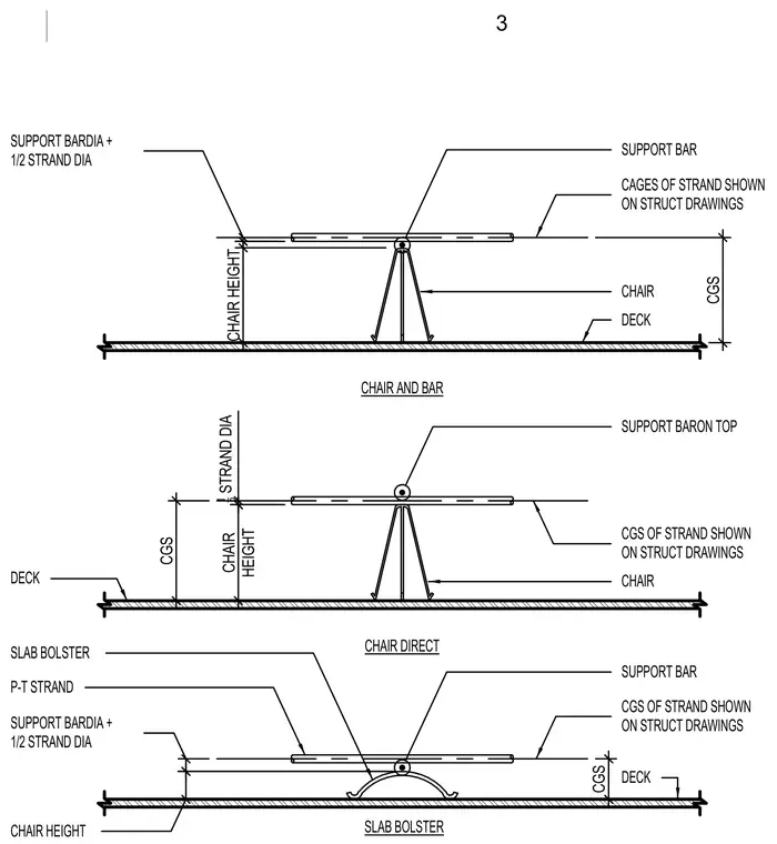
Post-tensioned tendon support assemblies utilize continuous chairs, support bars, and slab bolsters resting directly on the structural deck. The chair supports a longitudinal support bar beneath or above the strand cages, establishing the specified center of gravity of steel dimension. Chair heights are calculated using the support bar diameter and one-half of the strand diameter. Cages of strand are positioned as shown on structural drawings and maintained at the exact center of gravity of strand height.
CAGES OF STRAND SHOWN ON STRUCT DRAWINGS SUPPORT BARON TOP CGS OF STRAND SHOWN ON STRUCT DRAWINGS CHAIR AND BAR CHAIR DIRECT DECK DECK DECK CGS OF STRAND SHOWN ON STRUCT DRAWINGS P-T STRAND SLAB BOLSTER CHAIR CHAIR SUPPORT BAR SUPPORT BAR SLAB BOLSTER SUPPORT BARDIA + 1/2 STRAND DIA CHAIR HEIGHT SUPPORT BARDIA + 1/2 STRAND DIA CGS CGS CGS CHAIR HEIGHT 1_ 2 STRAND DIA CHAIR HEIGHT 3
Members view this detail in full resolution, download the CAD files (SVG, PDF), and can adapt it in the built-in CAD editor — export DXF, DWG, or PDF.
Start membership