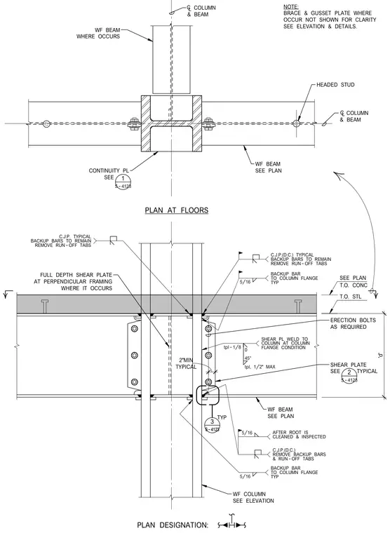
A two-sided structural steel moment connection joins wide-flange beams to a wide-flange column. The connection incorporates continuity plates welded to the column flanges with complete joint penetration welds, utilizing backup bars that remain in place where specified and run-off tabs that are subsequently removed. A full-depth shear plate is provided at perpendicular framing where it occurs, secured with erection bolts as required to the column flange. Fillet welds of five-sixteenths inch size are specified after root inspection, alongside specific edge preparation and beveling conditions for the shear plate welds. Headed studs are embedded in the concrete floor slab bearing on the steel framing.
TYPICAL 2"MIN PLAN AT FLOORS HEADED STUD WF BEAM SEE PLAN COLUMN & BEAM C L WF BEAM WHERE OCCURS CONTINUITY PL SEE BACKUP BARS TO REMAIN C.J.P.(D.C.) TYPICAL REMOVE RUN-OFF TABS SEE PLAN T.O. CONC T.O. STL SHEAR PLATE SEE TYPICAL WF BEAM SEE PLAN WF COLUMN SEE ELEVATION TYP REMOVE BACKUP BARS C.J.P.(D.C.) & RUN-OFF TABS CLEANED & INSPECTED 5/16 AFTER ROOT IS COLUMN & BEAM C L FULL DEPTH SHEAR PLATE AT PERPENDICULAR FRAMING WHERE IT OCCURS ERECTION BOLTS AS REQUIRED TO COLUMN FLANGE 5/16 BACKUP BAR TYP TO COLUMN FLANGE 5/16 BACKUP BAR TYP NOTE: BRACE & GUSSET PLATE WHERE OCCUR NOT SHOWN FOR CLARITY SEE ELEVATION & DETAILS. BACKUP BARS TO REMAIN C.J.P. TYPICAL REMOVE RUN-OFF TABS 'd' S-4123 3 COLUMN AT COLUMN tpl-1/8 SHEAR PL WELD TO FLANGE CONDITION 0 45° tpl, 1/2" MAX S-4123 1 S-4123 2 PLAN DESIGNATION:
Members view this detail in full resolution, download the CAD files (SVG, PDF), and can adapt it in the built-in CAD editor — export DXF, DWG, or PDF.
Start membership