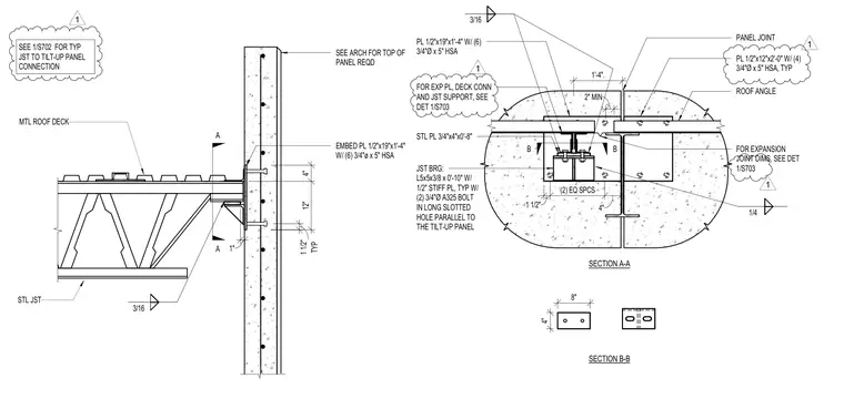
A steel roof joist bears on an L5x5x3/8 by ten-inch angle with a one-half-inch stiffener plate, fastened with two three-quarter-inch diameter A325 bolts in long slotted holes parallel to the tilt-up panel, at a tilt-up concrete wall panel featuring an expansion joint. A one-half-inch by nineteen-inch by one-foot-four-inch embed plate with six three-quarter-inch diameter by five-inch heavy stud anchors secures the assembly into the concrete wall. Panel joints utilize a one-half-inch by twelve-inch by two-foot plate with four three-quarter-inch diameter heavy stud anchors. Fillet welds of three-sixteenths and one-quarter inch size are specified throughout the connection components.
A A B B 2" MIN SEE ARCH FOR TOP OF PANEL REQD EMBED PL 1/2"x19"x1'-4" W/ (6) 3/4"ø x 5" HSA MTL ROOF DECK 12" 4" TYP 1 1/2" STL JST SEE 1/S702 FOR TYP JST TO TILT-UP PANEL CONNECTION 1" SECTION A-A 4" 8" SECTION B-B 1'-4". 1 1/2" (2) EQ SPCS 4" PANEL JOINT PL 1/2"x12"x2'-0" W/ (4) 3/4"Ø x 5" HSA, TYP ROOF ANGLE PL 1/2"x19"x1'-4" W/ (6) 3/4"Ø x 5" HSA STL PL 3/4"x4"x0'-8" JST BRG: L5x5x3/8 x 0'-10" W/ 1/2" STIFF PL, TYP W/ (2) 3/4"Ø A325 BOLT IN LONG SLOTTED HOLE PARALLEL TO THE TILT-UP PANEL 3/16 3/16 1/4 FOR EXP PL, DECK CONN AND JST SUPPORT, SEE DET 1/S703 FOR EXPANSION JOINT DIMS, SEE DET 1/S703 1 1 1 1
Members view this detail in full resolution, download the CAD files (SVG, PDF), and can adapt it in the built-in CAD editor — export DXF, DWG, or PDF.
Start membership