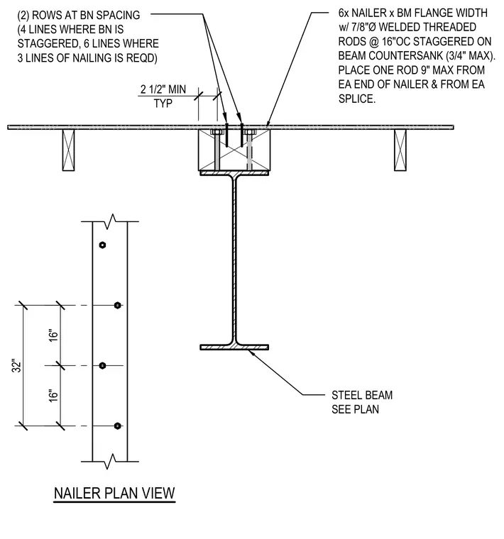
A six-inch nominal wood nailer is secured to the steel beam flange using seven-eighths-inch diameter welded threaded rods spaced at sixteen inches on center staggered across the beam with a maximum three-quarter-inch countersank depth. One threaded rod is placed within nine inches maximum from each end of the nailer and from each splice. Nailing requires two rows at bolt nail spacing, with four lines where the bolt nail is staggered and six lines where three lines of nailing are required, maintaining a two-and-one-half-inch minimum typically. The steel beam size is per plan.
6x NAILER x BM FLANGE WIDTH w/ 7/8"Ø WELDED THREADED RODS @ 16"OC STAGGERED ON BEAM COUNTERSANK (3/4" MAX). PLACE ONE ROD 9" MAX FROM EA END OF NAILER & FROM EA SPLICE. STEEL BEAM SEE PLAN 16" 16" 32" NAILER PLAN VIEW (2) ROWS AT BN SPACING (4 LINES WHERE BN IS STAGGERED, 6 LINES WHERE 3 LINES OF NAILING IS REQD) 2 1/2" MIN TYP
Members view this detail in full resolution, download the CAD files (SVG, PDF), and can adapt it in the built-in CAD editor — export DXF, DWG, or PDF.
Start membership