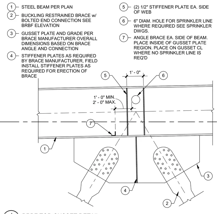
A buckling restrained brace top connection frames into a structural steel beam as specified per the structural plan. The assembly incorporates a gusset plate sized according to the brace manufacturer requirements based on the brace angle and connection geometry. Additional stiffener plates, including two half-inch plates on each side of the beam web, are field installed as required for brace erection and manufacturer specifications. An optional six-inch diameter hole is provided in the beam web for a sprinkler line where required by mechanical drawings. Angle braces are placed on each side of the beam within the gusset plate region or on the gusset centerline where no sprinkler line is required.
2' - 0" MAX. 1' - 0" MIN. 1' - 0" 1 STEEL BEAM PER PLAN 1 2 BUCKLING RESTRAINED BRACE w/ BOLTED END CONNECTION SEE BRBF ELEVATION 3 GUSSET PLATE AND GRADE PER BRACE MANUFACTURER OVERALL DIMENSIONS BASED ON BRACE ANGLE AND CONNECTION 4 STIFFENER PLATES AS REQUIRED BY BRACE MANUFACTURER, FIELD INSTALL STIFFENER PLATES AS REQUIRED FOR ERECTION OF BRACE 5 (2) 1/2" STIFFENER PLATE EA. SIDE OF WEB 6 6" DIAM. HOLE FOR SPRINKLER LINE WHERE REQUIRED SEE SPRINKLER DWGS. 7 ANGLE BRACE EA. SIDE OF BEAM. PLACE INSIDE OF GUSSET PLATE REGION. PLACE ON GUSSET CL WHERE NO SPRINKLER LINE IS REQ'D 2 3 4 6 5 7
Members view this detail in full resolution, download the CAD files (SVG, PDF), and can adapt it in the built-in CAD editor — export DXF, DWG, or PDF.
Start membership