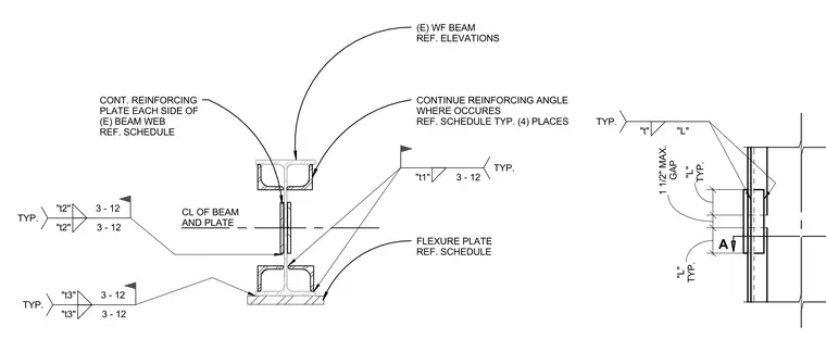
An existing wide flange beam is reinforced with continuous plates placed on each side of the beam web, referenced from the schedule. Continuous reinforcing angles are detailed at four places where required, maintaining a typical one and a half inch maximum gap. Flexure plates are added to the beam flanges with specific weld symbols and sizes designated by variables t1, t2, and t3. Field welds with flag symbols indicate field-applied connections for the reinforcing elements.
"L" TYP. 1 1/2" MAX. GAP "L" TYP. "t" "L" TYP. A CL OF BEAM AND PLATE "t1" 3 - 12 TYP. "t2" 3 - 12 "t2" 3 - 12 TYP. (E) WF BEAM REF. ELEVATIONS CONT. REINFORCING PLATE EACH SIDE OF (E) BEAM WEB REF. SCHEDULE CONTINUE REINFORCING ANGLE WHERE OCCURES REF. SCHEDULE TYP. (4) PLACES "t3" 3 - 12 "t3" 3 - 12 TYP. FLEXURE PLATE REF. SCHEDULE
Members view this detail in full resolution, download the CAD files (SVG, PDF), and can adapt it in the built-in CAD editor — export DXF, DWG, or PDF.
Start membership