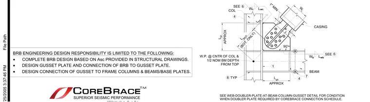
A buckling-restrained brace connects at its bottom to a steel column and beam assembly via a gusset plate using multiple bolts, maintaining a one-inch minimum clearance from the casing. A work point is established at the center of the column and one-half the nominal beam depth from the top. Additional web doubler plates are required at the beam-column-gusset intersection when specified by the connection schedule. Engineering design responsibilities for the buckling-restrained brace include complete brace design based on specified core area, gusset plate design, and framing connections.
L gc APPROX COL 4 W.P. @ CNTR OF COL & 1/2 NOM BM DEPTH FROM TOP L gb APPROX 6 SEE W b BEAM 90° 6 SEE W c X X 7 4 1 L wc L wb 8 TYP SEE WEB-DOUBLER-PLATE-AT-BEAM-COLUMN-GUSSET DETAIL FOR CONDITION WHEN DOUBLER PLATE REQUIRED BY COREBRACE CONNECTION SCHEDULE. e L bh L wp-h (BOT. ONLY) CASING 1" MIN W L BRB ENGINEERING DESIGN RESPONSIBILITY IS LIMITED TO THE FOLLOWING: · COMPLETE BRB DESIGN BASED ON Asc PROVIDED IN STRUCTURAL DRAWINGS. · DESIGN GUSSET PLATE AND CONNECTION OF BRB TO GUSSET PLATE. · DESIGN CONNECTION OF GUSSET TO FRAME COLUMNS & BEAMS/BASE PLATES. SUPERIOR SEISMIC PERFORMANCE File Path
Members view this detail in full resolution, download the CAD files (SVG, PDF), and can adapt it in the built-in CAD editor — export DXF, DWG, or PDF.
Start membership