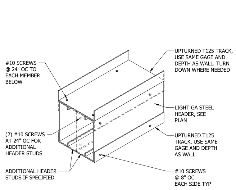
A cold-formed steel header framing assembly incorporates a light-gauge steel header paired with upturned T125 tracks matching the depth and gauge of the wall framing. The assembly is secured using number 10 screws spaced at eight inches on center on each side typically, with additional header studs fastened using two number 10 screws at 24 inches on center. The upturned track is oriented to turn down where needed based on field conditions and plan requirements.
ADDITIONAL HEADER STUDS IF SPECIFIED #10 SCREWS @ 24" OC TO EACH MEMBER BELOW UPTURNED T125 TRACK, USE SAME GAGE AND DEPTH AS WALL. TURN DOWN WHERE NEEDED LIGHT GA STEEL HEADER, SEE PLAN UPTURNED T125 TRACK, USE SAME GAGE AND DEPTH AS WALL #10 SCREWS @ 8" OC EACH SIDE TYP (2) #10 SCREWS AT 24" OC FOR ADDITIONAL HEADER STUDS
Members view this detail in full resolution, download the CAD files (SVG, PDF), and can adapt it in the built-in CAD editor — export DXF, DWG, or PDF.
Start membership