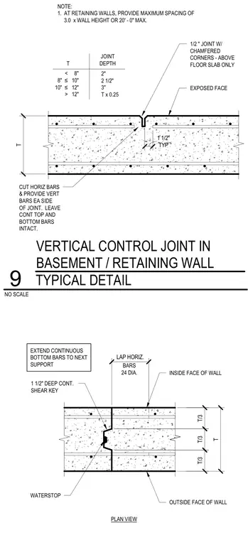
This concrete retaining and basement wall control joint detail shows a vertical joint with chamfered corners above the floor slab only and an exposed face. Horizontal reinforcing bars are cut at the joint with vertical bars provided on each side, while continuous top and bottom bars are left intact. A continuous one and a half inch deep shear key and a waterstop are embedded within the wall thickness. A joint depth table specifies depths corresponding to various wall thicknesses, and retaining walls require a maximum spacing of three times the wall height or twenty feet.
EXTEND CONTINUOUS BOTTOM BARS TO NEXT SUPPORT PLAN VIEW INSIDE FACE OF WALL OUTSIDE FACE OF WALL 1 1/2" DEEP CONT. SHEAR KEY T T/3 T/3 T/3 LAP HORIZ. BARS 24 DIA. WATERSTOP T VERTICAL CONTROL JOINT IN BASEMENT / RETAINING WALL 1/2 " JOINT W/ CHAMFERED CORNERS - ABOVE FLOOR SLAB ONLY EXPOSED FACE CUT HORIZ BARS & PROVIDE VERT BARS EA SIDE OF JOINT. LEAVE CONT TOP AND BOTTOM BARS INTACT. T JOINT DEPTH TYP 1 1/2" 2" 2 1/2" 3" T x 0.25 < 8" 8" ≤ 10" 10" ≤ 12" > 12" NOTE: 1. AT RETAINING WALLS, PROVIDE MAXIMUM SPACING OF 3.0 x WALL HEIGHT OR 20' - 0" MAX. TYPICAL DETAIL NO SCALE 9
Members view this detail in full resolution, download the CAD files (SVG, PDF), and can adapt it in the built-in CAD editor — export DXF, DWG, or PDF.
Start membership