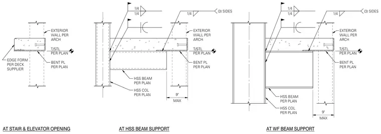
The assembly features a concrete slab edge supported by a bent plate and edge form at stair and elevator openings, or bearing on hollow structural section and wide flange beams connected to hollow structural section columns. A bent plate spans the slab edge, welded with one-quarter-inch fillets on three sides where applicable. Exterior walls and top of steel elevations are located per architectural and structural plans. Maximum nine-inch overhangs are maintained at beam supports.
AT STAIR & ELEVATOR OPENING BENT PL PER PLAN T/STL PER PLAN EXTERIOR WALL PER ARCH EDGE FORM PER DECK SUPPLIER AT HSS BEAM SUPPORT MAX 9" 1/4 1/4 1/4 (3) SIDES HSS BEAM PER PLAN HSS COL PER PLAN BENT PL PER PLAN T/STL PER PLAN EXTERIOR WALL PER ARCH AT WF BEAM SUPPORT MAX 9" 1/4 1/4 1/4 (3) SIDES HSS BEAM PER PLAN HSS COL PER PLAN BENT PL PER PLAN T/STL PER PLAN EXTERIOR WALL PER ARCH
Members view this detail in full resolution, download the CAD files (SVG, PDF), and can adapt it in the built-in CAD editor — export DXF, DWG, or PDF.
Start membership