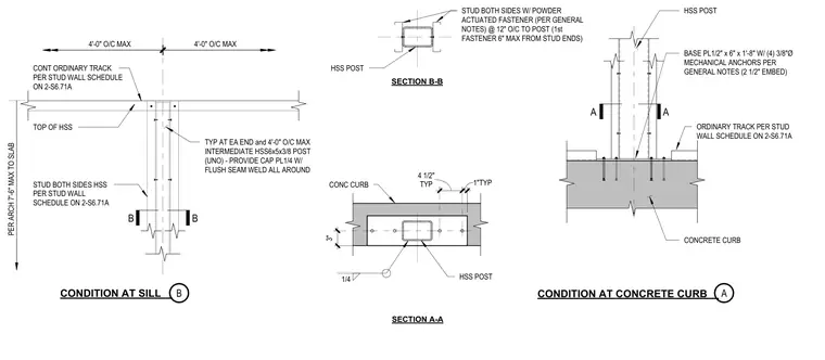
An intermediate hollow structural section post measuring six by five by three-eighths inches is anchored at its base to a concrete curb using a one-half by six-inch by one-foot-eight-inch base plate secured by four three-eighths-inch diameter mechanical anchors with a two-and-one-half-inch embedment depth. Steel studs are attached to both sides of the hollow structural section post using powder-actuated fasteners spaced at twelve inches on center, with the first fastener located a maximum of six inches from the stud ends. A continuous ordinary track is positioned per the stud wall schedule atop the assembly. The hollow structural section post is capped with a one-quarter-inch plate featuring a flush seam weld all around. Plan sections through the wall and curb detail the stud attachment and concrete cover dimensions.
B B 4'-0" O/C MAX 4'-0" O/C MAX CONT ORDINARY TRACK PER STUD WALL SCHEDULE ON 2-S6.71A TOP OF HSS PER ARCH 7'-6" MAX TO SLAB STUD BOTH SIDES HSS PER STUD WALL SCHEDULE ON 2-S6.71A TYP AT EA END and 4'-0" O/C MAX INTERMEDIATE HSS6x5x3/8 POST (UNO) - PROVIDE CAP PL1/4 W/ FLUSH SEAM WELD ALL AROUND STUD BOTH SIDES W/ POWDER ACTUATED FASTENER (PER GENERAL NOTES) @ 12" O/C TO POST (1st FASTENER 6" MAX FROM STUD ENDS) HSS POST SECTION B-B CONDITION AT SILL CONDITION AT CONCRETE CURB A A HSS POST BASE PL1/2" x 6" x 1'-8" W/ (4) 3/8"Ø MECHANICAL ANCHORS PER GENERAL NOTES (2 1/2" EMBED) ORDINARY TRACK PER STUD WALL SCHEDULE ON 2-S6.71A CONCRETE CURB CONC CURB SECTION A-A TYP 4 1/2" 1"TYP 1/4 A B 3" HSS POST
Members view this detail in full resolution, download the CAD files (SVG, PDF), and can adapt it in the built-in CAD editor — export DXF, DWG, or PDF.
Start membership