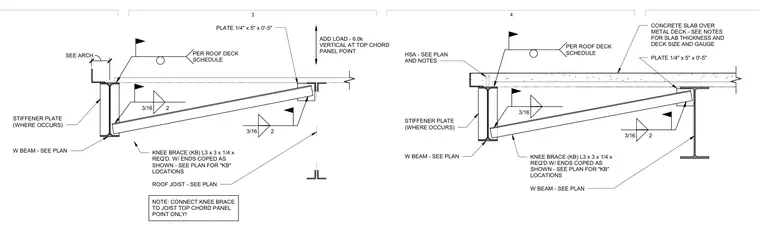
A knee brace connection stabilizes a roof joist oriented perpendicularly to a wide flange beam. The assembly incorporates an L3 x 3 x 1/4 angle knee brace with coped ends connected to the joist top chord panel point and the supporting W-beam. A 1/4 inch by 5 inch by 0'-5 inch plate and a stiffener plate are included where specified by the structural plan. Fillet welds of 3/16 inch size secure the connection components, and an additional vertical load of 6.0 kips is accommodated at the top chord panel point per the roof deck schedule. The drawing notes mandate that the knee brace must connect strictly to the joist top chord panel point.
NOTE: CONNECT KNEE BRACE TO JOIST TOP CHORD PANEL POINT ONLY! KNEE BRACE (KB) L3 x 3 x 1/4 x REQ'D. W/ ENDS COPED AS SHOWN - SEE PLAN FOR "KB" LOCATIONS W BEAM - SEE PLAN STIFFENER PLATE (WHERE OCCURS) ROOF JOIST - SEE PLAN ADD LOAD - 6.0k VERTICAL AT TOP CHORD PANEL POINT PER ROOF DECK SCHEDULE 3/16 2 3/16 2 SEE ARCH. PLATE 1/4" x 5" x 0'-5" KNEE BRACE (KB) L3 x 3 x 1/4 x REQ'D W/ ENDS COPED AS SHOWN - SEE PLAN FOR "KB" LOCATIONS W BEAM - SEE PLAN STIFFENER PLATE (WHERE OCCURS) W BEAM - SEE PLAN CONCRETE SLAB OVER METAL DECK - SEE NOTES FOR SLAB THICKNESS AND DECK SIZE AND GAUGE HSA - SEE PLAN AND NOTES PER ROOF DECK SCHEDULE 3/16 2 3/16 PLATE 1/4" x 5" x 0'-5" 3 4
Members view this detail in full resolution, download the CAD files (SVG, PDF), and can adapt it in the built-in CAD editor — export DXF, DWG, or PDF.
Start membership