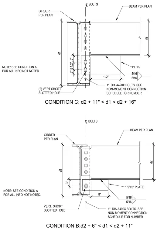
Non-moment steel beam to girder connections feature bolted shear tabs welded to the supporting girder web. The assembly utilizes one-inch diameter A490X high-strength bolts, with the quantity determined per the non-moment connection schedule. A one-half-inch thick plate connects the supported beam, welded top and bottom with five-sixteenth-inch fillet welds. Vertical short slotted holes are incorporated into the connection to accommodate specific dimensional ranges denoted as Condition B and Condition C.
GIRDER PER PLAN BEAM PER PLAN C L BOLTS 1" DIA A490X BOLTS. SEE NON-MOMENT CONNECTION SCHEDULE FOR NUMBER 8" d2 d1 1/2"x5" PLATE CONDITION B:d2 + 6" < d1 < d2 + 11" 3" VERT. SHORT SLOTTED HOLE NOTE: SEE CONDITION A FOR ALL INFO NOT NOTED. 5/16 5/16 GIRDER PER PLAN BEAM PER PLAN C L BOLTS 1" DIA A490X BOLTS. SEE NON-MOMENT CONNECTION SCHEDULE FOR NUMBER 1'-2" d2 d1 PL 1/2 CONDITION C: d2 + 11" < d1 < d2 + 16" 2" 3 1/2" 3" (2) VERT SHORT SLOTTED HOLE NOTE: SEE CONDITION A FOR ALL INFO NOT NOTED. 5/16 5/16
Members view this detail in full resolution, download the CAD files (SVG, PDF), and can adapt it in the built-in CAD editor — export DXF, DWG, or PDF.
Start membership