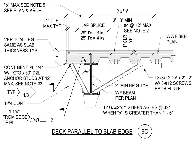
A structural detail features a concrete slab edge running parallel to a wide flange beam per plan. The assembly incorporates a continuous one-quarter-inch bent plate with half-inch diameter by thirty-inch D2L anchor studs spaced at twelve inches maximum. A vertical leg matches the slab thickness, and welded wire fabric is installed throughout the slab. Number four reinforcing bars are provided continuously and at twelve inches maximum spacing with lap splices varying based on concrete compressive strengths of three ksi or four ksi. Where dimension b exceeds one foot six inches, twelve gauge by two-inch by two-inch stiffener angles are spaced at thirty-two inches on center. Additionally, three-inch by three-inch by twelve gauge angles measuring two feet two inches long are secured with three number twelve screws in each flute.
VERTICAL LEG SAME AS SLAB THICKNESS TYP 12 GAx2"x2" STIFFN AGLES @ 32" WHEN "b" IS GREATER THAN 1' - 6" L3x3x12 GA x 2' - 2" W/ 3-#12 SCREWS EACH FLUTE WF BEAM PER PLAN #4 @ 12" MAX SEE NOTE 2 WWF SEE PLAN CONT BENT PL 1/4" W/ 1/2"Ø x 30" D2L ANCHOR STUDS AT 12" MAX, SEE NOTE #3 DECK PARALLEL TO SLAB EDGE "b" MAX SEE NOTE 5 SEE PLAN & ARCH 1-#4 CONT 3/4Ø 12 CL 1 1/4" FROM EDGE OF PL 1/8 TYP 2" MIN BR'G TYP LAP SPLICE MAX TYP 1" CLR 3' - 0" MIN 2 x "b" TYP 1" CLR 29" f'c = 3 ksi 25" f'c = 4 ksi 6C
Members view this detail in full resolution, download the CAD files (SVG, PDF), and can adapt it in the built-in CAD editor — export DXF, DWG, or PDF.
Start membership