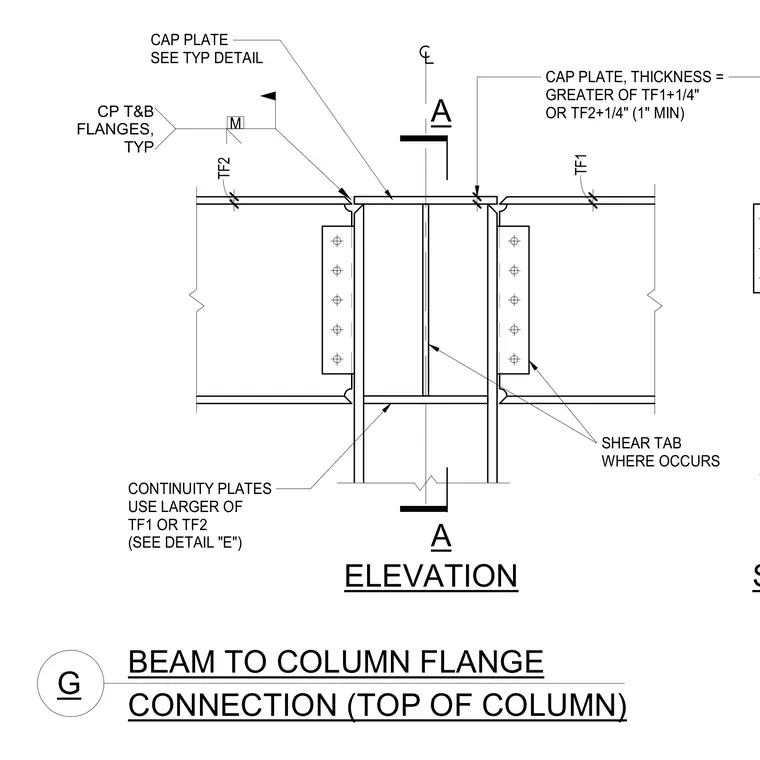
This structural steel connection joins beams framing into opposite sides of a column flange at the top of the column. A cap plate sits atop the column, with its thickness sized to the greater of the connected beam flange thicknesses plus one-quarter inch with a one-inch minimum. Beams connect to the column flange using shear tabs welded to the column and bolted to the beam webs. Continuity plates welded between the column flanges are aligned with the top and bottom flanges of the framing beams, with thicknesses determined by the respective beam flange sizes.
A A BEAM TO COLUMN FLANGE G CONNECTION (TOP OF COLUMN) SECTION A-A ELEVATION CONTINUITY PLATES USE LARGER OF TF1 OR TF2 (SEE DETAIL "E") CAP PLATE, THICKNESS = GREATER OF TF1+1/4" OR TF2+1/4" (1" MIN) TF2 TF1 . CP T&B FLANGES, TYP M CAP PLATE SEE TYP DETAIL SHEAR TAB WHERE OCCURS
Members view this detail in full resolution, download the CAD files (SVG, PDF), and can adapt it in the built-in CAD editor — export DXF, DWG, or PDF.
Start membership