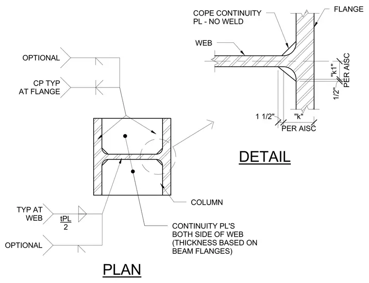
Continuity plates are positioned on both sides of the column web, with their thickness determined by the connecting beam flanges. The assembly includes a detailed plan view of the column profile and an enlarged detail of the web-to-flange intersection showing a cope with no weld extending one-half inch per AISC dimension k1, and one and one-half inches per AISC dimension k. Optional continuity plates are indicated at both the web and flange locations, with specific plate thickness noted as plate thickness divided by two at the web.
DETAIL PLAN COLUMN WEB FLANGE COPE CONTINUITY PL - NO WELD 1/2" PER AISC "k1" 1 1/2" PER AISC "k" CONTINUITY PL'S BOTH SIDE OF WEB (THICKNESS BASED ON BEAM FLANGES) OPTIONAL TYP AT WEB tPL 2 OPTIONAL CP TYP AT FLANGE
Members view this detail in full resolution, download the CAD files (SVG, PDF), and can adapt it in the built-in CAD editor — export DXF, DWG, or PDF.
Start membership