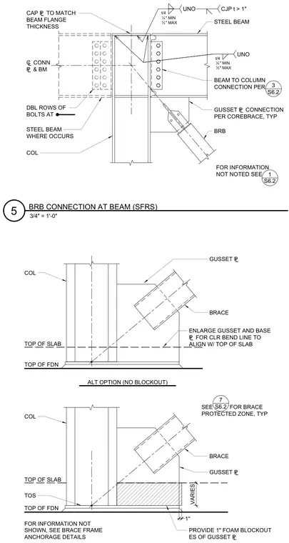
A buckling-restrained brace connects at a steel beam and column framing junction within a seismic force-resisting system. A gusset plate is welded to the column and beam, with a cap plate matching the beam flange thickness. A buckling-restrained brace connects via a gusset plate connection per CoreBrace specifications. Two details show alternative conditions at the foundation level, featuring a one-inch foam blockout at each side of the gusset plate or an alternate option with an enlarged gusset and base plate to align the bend line with the top of the slab.
TOP OF SLAB PROVIDE 1" FOAM BLOCKOUT ES OF GUSSET £ SEE FOR BRACE PROTECTED ZONE, TYP VARIES TOS TOP OF FDN COL TOP OF SLAB TOP OF FDN COL GUSSET £ ALT OPTION (NO BLOCKOUT) ENLARGE GUSSET AND BASE £ FOR CLR BEND LINE TO ALIGN W/ TOP OF SLAB 7 S6.2 BRACE GUSSET £ BRACE 1" FOR INFORMATION NOT SHOWN, SEE BRACE FRAME ANCHORAGE DETAILS FOR INFORMATION NOT NOTED SEE 1 S6.2 ¢ CONN £ & BM STEEL BEAM WHERE OCCURS STEEL BEAM GUSSET £ CONNECTION PER COREBRACE, TYP BRB COL BEAM TO COLUMN CONNECTION PER DBL ROWS OF BOLTS AT 3 S6.2 CJP t > 1" UNO t/4 Ë" MIN Ï" MAX UNO t/4 Ë" MIN Ï" MAX CAP £ TO MATCH BEAM FLANGE THICKNESS 3/4" = 1'-0" 5 BRB CONNECTION AT BEAM (SFRS)
Members view this detail in full resolution, download the CAD files (SVG, PDF), and can adapt it in the built-in CAD editor — export DXF, DWG, or PDF.
Start membership