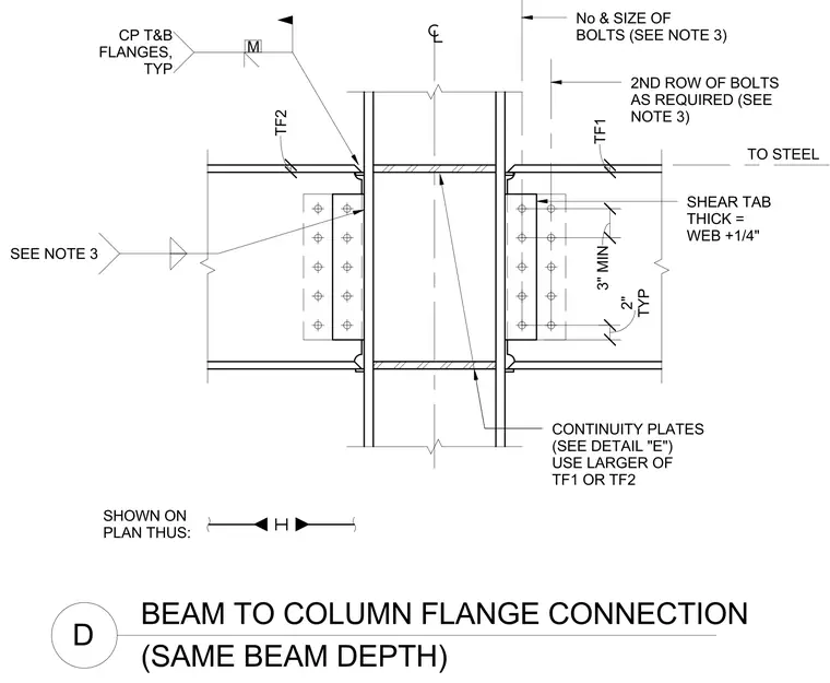
Steel beams frame into opposite sides of a structural steel column flange using a bolted single plate shear tab and top and bottom continuity plates. The shear tab thickness is specified as the beam web thickness plus one-quarter inch, fastened with a vertical row of bolts sized and numbered per general structural notes with a second row added when required. Continuity plates match the larger flange thickness of the two framing beams and weld to the column flanges with typical moment connection details. A three-inch minimum vertical spacing applies between bolt groups with standard two-inch dimensions shown on plan.
BEAM TO COLUMN FLANGE CONNECTION D (SAME BEAM DEPTH) TO STEEL No & SIZE OF BOLTS (SEE NOTE 3) 2ND ROW OF BOLTS AS REQUIRED (SEE NOTE 3) CONTINUITY PLATES (SEE DETAIL "E") USE LARGER OF TF1 OR TF2 SHEAR TAB THICK = WEB +1/4" TF2 TF1 3" MIN TYP 2" SHOWN ON PLAN THUS: SEE NOTE 3 CP T&B FLANGES, TYP M
Members view this detail in full resolution, download the CAD files (SVG, PDF), and can adapt it in the built-in CAD editor — export DXF, DWG, or PDF.
Start membership