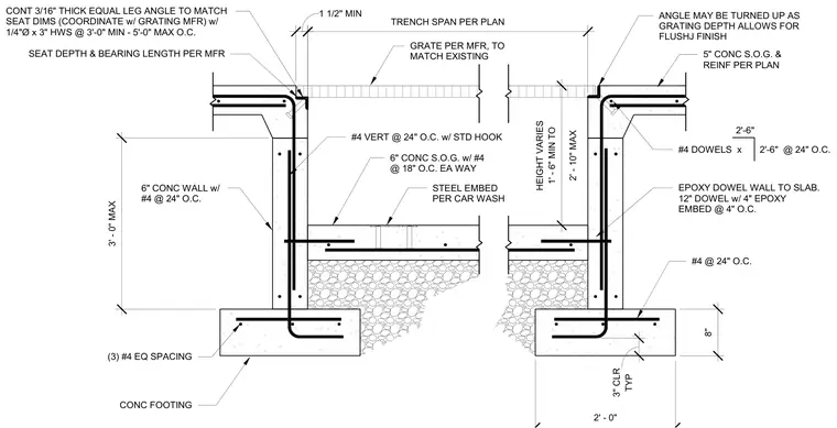
A concrete conveyor trench section features cast-in-place concrete walls, continuous concrete footings, and a five-inch concrete slab on grade. The trench walls are reinforced with number four vertical bars at twenty-four inches on center with standard hooks, and the footing includes three number four bars with equal spacing. A continuous three-sixteenths inch thick equal leg angle is embedded at the top of the wall with one-quarter inch diameter by three-inch heavy-weight studs spaced between three and five feet on center to support grating per the manufacturer. Epoxy dowels measuring twelve inches with four-inch epoxy embeds at four inches on center tie the wall to the slab. Additional reinforcement includes number four dowels at two feet six inches on center and number four bars at eighteen inches on center each way in the slab.
TRENCH SPAN PER PLAN 3' - 0" MAX 2' - 10" MAX HEIGHT VARIES 1' - 6" MIN TO 6" CONC WALL w/ #4 @ 24" O.C. SEAT DEPTH & BEARING LENGTH PER MFR #4 VERT @ 24" O.C. w/ STD HOOK STEEL EMBED PER CAR WASH (3) #4 EQ SPACING CONC FOOTING 6" CONC S.O.G. w/ #4 @ 18" O.C. EA WAY GRATE PER MFR, TO MATCH EXISTING CONT 3/16" THICK EQUAL LEG ANGLE TO MATCH SEAT DIMS (COORDINATE w/ GRATING MFR) w/ 1/4"Ø x 3" HWS @ 3'-0" MIN - 5'-0" MAX O.C. 5" CONC S.O.G. & REINF PER PLAN #4 DOWELS x 2'-6" @ 24" O.C. 2'-6" ANGLE MAY BE TURNED UP AS GRATING DEPTH ALLOWS FOR FLUSHJ FINISH EPOXY DOWEL WALL TO SLAB. 12" DOWEL w/ 4" EPOXY EMBED @ 4" O.C. TYP 3" CLR 2' - 0" 8" 1 1/2" MIN #4 @ 24" O.C.
Members view this detail in full resolution, download the CAD files (SVG, PDF), and can adapt it in the built-in CAD editor — export DXF, DWG, or PDF.
Start membership