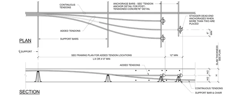
Post-tensioned concrete slab reinforcement layout showing added tendons, continuous tendons, and dead-end anchorage positioning. Added tendons terminate at staggered dead-end anchorages spaced a minimum of six inches apart, positioned twelve inches minimum from supports. Support bars and chairs maintain tendon profiles throughout the span, with added tendon locations specified per the framing plan. Dead-end anchorages are staggered when more than two are placed along the same line.
SLAB THICKNESS SEE PLAN PLAN SECTION STAGGER DEAD-END ANCHORAGES WHEN MORE THAN TWO ARE PLACED ANCHORAGE BARS - SEE "TENDON ANCHOR DETAIL FOR POST- TENSIONED CONCRETE" DETAIL CONTINUOUS TENDONS ADDED TENDONS CONTINUOUS TENDONS SUPPORT BARS ADDED TENDONS SUPPORT H/2 H/2 H L/4 OR 4'-0" MIN SEE FRAMING PLAN FOR ADDED TENDON LOCATIONS 12" MIN MIN 6" SUPPORT BAR & CHAIR
Members view this detail in full resolution, download the CAD files (SVG, PDF), and can adapt it in the built-in CAD editor — export DXF, DWG, or PDF.
Start membership