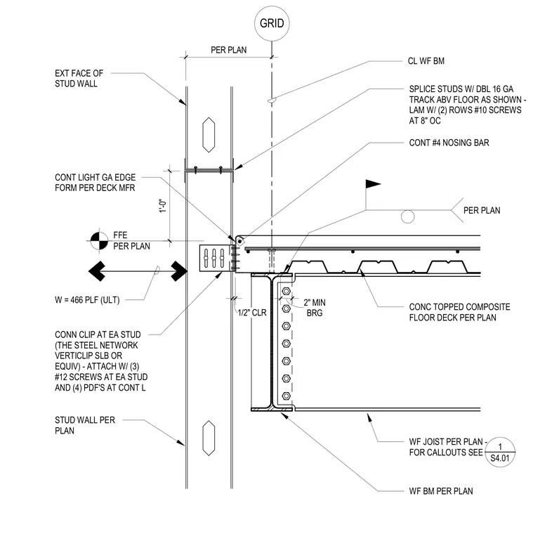
A continuous cold-formed metal stud wall aligns vertically with a floor assembly, incorporating double 16-gauge track splices above the floor laminated with two rows of number 10 screws at eight inches on center. A vertical slip clip, such as The Steel Network Verticlip SLB or equivalent, provides a half-inch clearance connection to each stud using three number 12 screws per stud and four powder-actuated fasteners at a continuous angle. The concrete-topped composite floor deck bears on a wide flange beam with a two-inch minimum bearing length and includes a continuous number four nosing bar and a continuous light-gauge edge form per the deck manufacturer. A wide flange joist supports the system per plan, and an ultimate design load of 466 pounds per linear foot is applied at the exterior face of the stud wall.
WF JOIST PER PLAN - FOR CALLOUTS SEE STUD WALL PER PLAN BRG 2" MIN PER PLAN FFE PER PLAN CONT #4 NOSING BAR CONT LIGHT GA EDGE FORM PER DECK MFR WF BM PER PLAN CL WF BM CONC TOPPED COMPOSITE FLOOR DECK PER PLAN 1/2" CLR CONN CLIP AT EA STUD (THE STEEL NETWORK VERTICLIP SLB OR EQUIV) - ATTACH W/ (3) #12 SCREWS AT EA STUD AND (4) PDF'S AT CONT L EXT FACE OF STUD WALL PER PLAN W = 466 PLF (ULT) _____ 1 S4.01 GRID 1'-0" SPLICE STUDS W/ DBL 16 GA TRACK ABV FLOOR AS SHOWN - LAM W/ (2) ROWS #10 SCREWS AT 8" OC
Members view this detail in full resolution, download the CAD files (SVG, PDF), and can adapt it in the built-in CAD editor — export DXF, DWG, or PDF.
Start membership