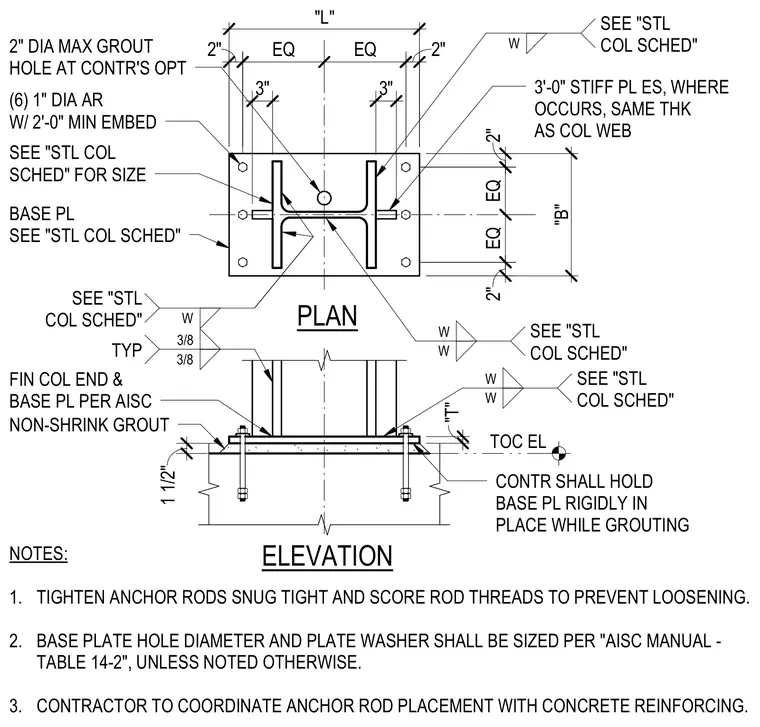
A steel column connects to a concrete foundation through a base plate secured by six one-inch diameter anchor rods with a two-foot minimum embedment. Three-foot stiffener plates are welded to each side of the column web matching the web thickness, with three-eighth-inch fillet welds specified at the column connections. A one-and-one-half-inch layer of non-shrink grout sits beneath the base plate, which includes a two-inch diameter maximum optional grout hole. The finished column end and base plate conform to AISC standards, and the contractor must hold the base plate rigidly in place during grouting while tightening anchor rods snug tight and scoring threads to prevent loosening.
TOC EL 2" DIA MAX GROUT HOLE AT CONTR'S OPT (6) 1" DIA AR W/ 2'-0" MIN EMBED SEE "STL COL SCHED" FOR SIZE BASE PL SEE "STL COL SCHED" FIN COL END & BASE PL PER AISC NON-SHRINK GROUT CONTR SHALL HOLD BASE PL RIGIDLY IN PLACE WHILE GROUTING SEE "STL COL SCHED" W W SEE "STL COL SCHED" W SEE "STL COL SCHED" W NOTES: 1. TIGHTEN ANCHOR RODS SNUG TIGHT AND SCORE ROD THREADS TO PREVENT LOOSENING. 2. BASE PLATE HOLE DIAMETER AND PLATE WASHER SHALL BE SIZED PER "AISC MANUAL - TABLE 14-2", UNLESS NOTED OTHERWISE. 3. CONTRACTOR TO COORDINATE ANCHOR ROD PLACEMENT WITH CONCRETE REINFORCING. ELEVATION PLAN 1" 1 1/2" 28" 18" "B" "L" "T" 2" 2" EQ EQ 2" 2" EQ EQ 3" 3" 3'-0" STIFF PL ES, WHERE OCCURS, SAME THK AS COL WEB SEE "STL COL SCHED" W W TYP 3/8 3/8
Members view this detail in full resolution, download the CAD files (SVG, PDF), and can adapt it in the built-in CAD editor — export DXF, DWG, or PDF.
Start membership