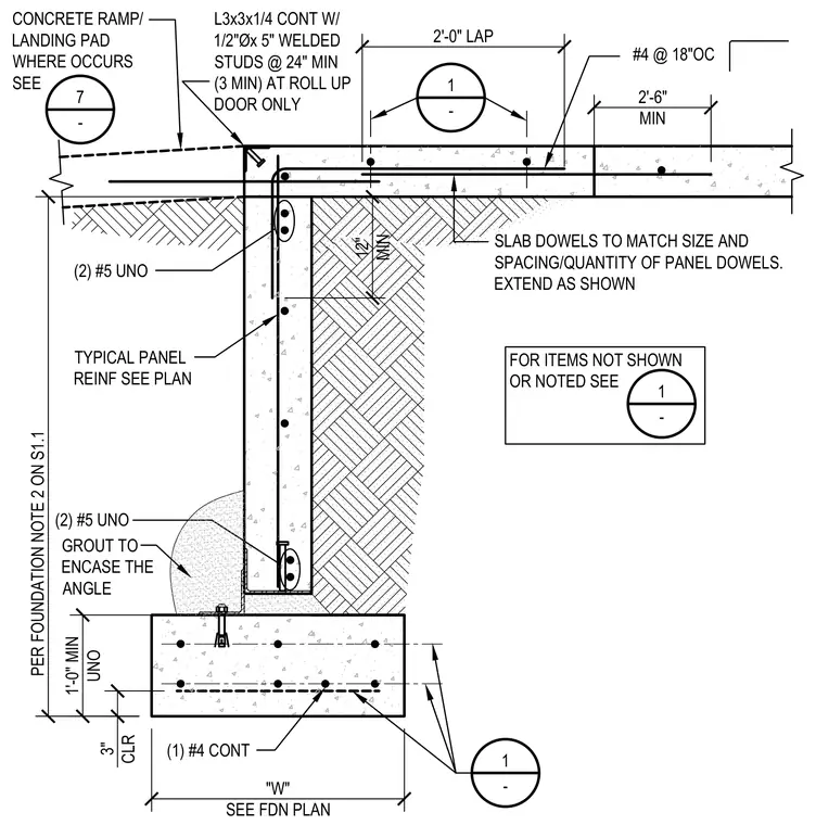
A concrete foundation footing supports a reinforced concrete wall with a slab-on-grade connection. The continuous footing has a width designated as W per the foundation plan with a depth of one foot minimum unless otherwise noted and features one continuous number four bottom rebar with three inches of clear cover. The vertical wall includes typical panel reinforcement of two number five bars unless otherwise noted, tied into the footing with slab dowels matching the size, spacing, and quantity of the panel dowels with a two-foot-six-inch minimum extension. At the roll-up door location, a continuous L3x3x1/4 angle with half-inch diameter by five-inch welded studs spaced at twenty-four inches minimum is cast into the edge and encased in grout. A concrete ramp or landing pad occurs at the top of the slab, which is reinforced with number four bars at eighteen inches on center and features a two-foot lap splice.
1'-0" MIN UNO 3" CLR (2) #5 UNO 1 - 1 - 2'-0" LAP 2'-6" MIN SLAB DOWELS TO MATCH SIZE AND SPACING/QUANTITY OF PANEL DOWELS. EXTEND AS SHOWN (2) #5 UNO TYPICAL PANEL REINF SEE PLAN CONCRETE RAMP/ LANDING PAD WHERE OCCURS SEE 7 - #4 @ 18"OC 12" MIN "W" SEE FDN PLAN (1) #4 CONT FOR ITEMS NOT SHOWN OR NOTED SEE 1 - PER FOUNDATION NOTE 2 ON S1.1 L3x3x1/4 CONT W/ 1/2"Øx 5" WELDED STUDS @ 24" MIN (3 MIN) AT ROLL UP DOOR ONLY GROUT TO ENCASE THE ANGLE
Members view this detail in full resolution, download the CAD files (SVG, PDF), and can adapt it in the built-in CAD editor — export DXF, DWG, or PDF.
Start membership