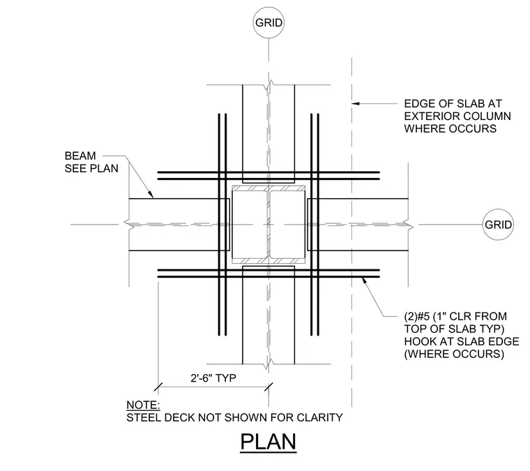
Additional reinforcing bars consisting of two number 5 bars with a one-inch clearance from the top of the slab are placed continuously around the column and beam framing intersection. These bars feature hooks at the slab edge where applicable and extend two feet six inches typically from the column centerline. The supporting steel framing beams are sized per the structural plan, and the steel deck is omitted for clarity.
NOTE: STEEL DECK NOT SHOWN FOR CLARITY BEAM SEE PLAN (2)#5 (1" CLR FROM TOP OF SLAB TYP) HOOK AT SLAB EDGE (WHERE OCCURS) EDGE OF SLAB AT EXTERIOR COLUMN WHERE OCCURS 2'-6" TYP PLAN GRID GRID
Members view this detail in full resolution, download the CAD files (SVG, PDF), and can adapt it in the built-in CAD editor — export DXF, DWG, or PDF.
Start membership