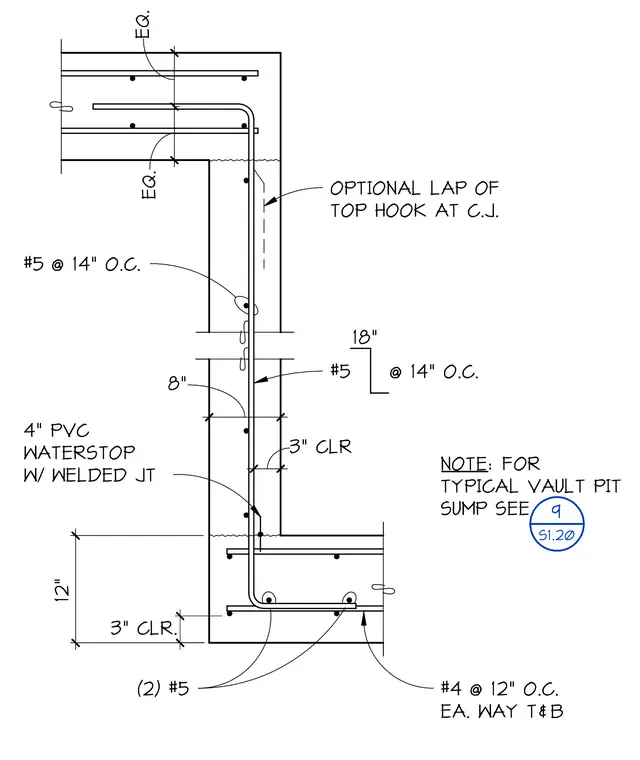
This subgrade electrical vault detail outlines a concrete wall and slab junction reinforced with number five bars spaced at fourteen inches on center vertically and number four bars spaced at twelve inches on center each way top and bottom in the slab. A four-inch polyvinyl chloride waterstop with a welded joint is positioned within the construction joint to prevent moisture penetration. The wall features an eight-inch thickness with three-inch clear cover and includes an optional lap of the top hook at the construction joint. Two number five bars reinforce the base slab section, maintaining three-inch clear cover from the bottom. A drawing reference note directs to sheet S1.20 for the typical vault pit sump.
OPTIONAL LAP OF TOP HOOK AT C.J. #5 @ 14" O.C. 4" PVC WATERSTOP W/ WELDED JT 12" #5 @ 14" O.C. 18" (2) #5 #4 @ 12" O.C. EA. WAY T&B 8" 3" CLR 3" CLR. EQ. EQ. NOTE: FOR TYPICAL VAULT PIT SUMP SEE 9 S1.20
Members view this detail in full resolution, download the CAD files (SVG, PDF), and can adapt it in the built-in CAD editor — export DXF, DWG, or PDF.
Start membership