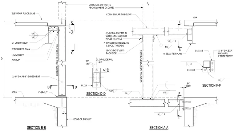
Elevator guiderail tube supports attach to structural steel framing and concrete pit slabs. The assembly incorporates guiderail tubes per schedule, connected with two three-quarter-inch diameter A307 machine bolts in vertical long slotted holes in angle angles, with nuts finger-tightened and threads spoiled. L6x3x3/8 by zero-foot-five long leg vertical angles are provided on each side. Three three-quarter-inch diameter expansion anchors with a six-inch embedment secure the base connection at the edge of the elevator pit, featuring a one-inch grout pad and two three-quarter-inch diameter anchor bolts with an eight-inch embedment.
F F E E C C D D MAX * * GUIDERAIL TUBE PER SCHEDULE GUIDERAIL SUPPORTS ABOVE (WHERE OCCURS) (2)-3/4"DIA A307 MB IN VERT LONG SLOTTED HOLES IN ANGLE FINGER TIGHTEN NUTS & SPOIL THREADS L6x3x3/8x0'-5" (LLV) EACH SIDE (3)-3/4"DIA EXP ANCHORS, 6" EMBEDMENT EDGE OF ELEV PIT 1" GROUT BASE (2)-3/4"DIA AB 8" EMBEDMENT PL 3/4 CL OF GUIDERAIL & PL GUIDERAIL TUBE PER SCHEDULE PL3/8x6" L6x6x3/8 LLV W BEAM PER PLAN (2)-L4x3x1/4 @20" W BEAM PER PLAN L4x4x3/8 L4x4x3/8 CONN SIMILAR TO BELOW ELEVATOR FLOOR SLAB SECTION F-F SECTION A-A SECTION B-B SECTION D-D MAX 3/4" 4" "H" GAP 1" 1/4 1/4 TYP 1/2" TYP 4" 5/16 1/4 1/4 1/4 1/4 5 3 1/4 1/4 5
Members view this detail in full resolution, download the CAD files (SVG, PDF), and can adapt it in the built-in CAD editor — export DXF, DWG, or PDF.
Start membership