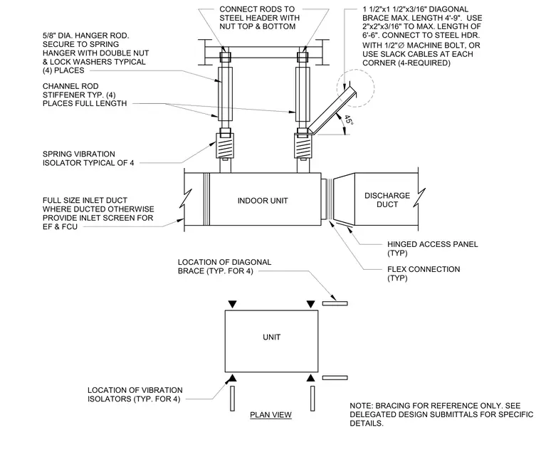
A structural suspension and vibration isolation assembly supports an indoor fan coil unit or in-line fan. Four five-eighths inch diameter hanger rods secure the unit to the overhead steel header using double nuts and lock washers at each spring hanger location. Four channel rod stiffeners run the full length of the hanger rods for added stability. Four one and one-half inch by one and one-half inch by three-sixteenths inch diagonal braces, or alternatively slack cables, connect the unit to the steel header with one-half inch diameter machine bolts. Flexible duct connections and a discharge duct with a hinged access panel attach to the unit, along with inlet ductwork or an inlet screen.
PLAN VIEW SPRING VIBRATION ISOLATOR TYPICAL OF 4 INDOOR UNIT 1 1/2"x1 1/2"x3/16" DIAGONAL BRACE MAX. LENGTH 4'-9". USE 2"x2"x3/16" TO MAX. LENGTH OF 6'-6". CONNECT TO STEEL HDR. WITH 1/2" ∅ MACHINE BOLT, OR USE SLACK CABLES AT EACH CORNER (4-REQUIRED) CONNECT RODS TO STEEL HEADER WITH NUT TOP & BOTTOM LOCATION OF DIAGONAL BRACE (TYP. FOR 4) UNIT LOCATION OF VIBRATION ISOLATORS (TYP. FOR 4) 5/8" DIA. HANGER ROD. SECURE TO SPRING HANGER WITH DOUBLE NUT & LOCK WASHERS TYPICAL (4) PLACES CHANNEL ROD STIFFENER TYP. (4) PLACES FULL LENGTH 45° DISCHARGE DUCT HINGED ACCESS PANEL (TYP) FLEX CONNECTION (TYP) FULL SIZE INLET DUCT WHERE DUCTED OTHERWISE PROVIDE INLET SCREEN FOR EF & FCU NOTE: BRACING FOR REFERENCE ONLY. SEE DELEGATED DESIGN SUBMITTALS FOR SPECIFIC DETAILS.
Members view this detail in full resolution, download the CAD files (SVG, PDF), and can adapt it in the built-in CAD editor — export DXF, DWG, or PDF.
Start membership