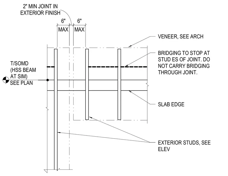
This plan detail shows a vertical joint in an exterior wall assembly detailing the cold-formed steel framing and slab edge condition. The exterior finish incorporates a two-inch minimum joint with a maximum six-inch dimension on either side of the joint centerline. Exterior studs are positioned as shown per the architectural elevation, with bridging terminating at the stud faces of the joint and left discontinuous across the expansion gap. A hollow structural section beam is indicated at the slab edge per plan.
MAX 6" EXTERIOR FINISH 2" MIN JOINT IN VENEER, SEE ARCH SLAB EDGE EXTERIOR STUDS, SEE ELEV MAX 6" SEE PLAN BRIDGING TO STOP AT STUD ES OF JOINT. DO NOT CARRY BRIDGING THROUGH JOINT. T/SOMD (HSS BEAM AT SIM)
Members view this detail in full resolution, download the CAD files (SVG, PDF), and can adapt it in the built-in CAD editor — export DXF, DWG, or PDF.
Start membership