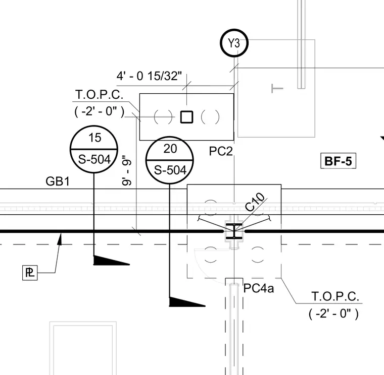
Precast concrete panels PC2 and PC4a, structural steel member C10, and grade beam GB1 are laid out in plan. Grid line Y3 establishes the alignment coordinate, with elevation markers indicating top of precast concrete at minus two feet zero inches. Dimension lines specify clearances of four feet zero and fifteen-thirty-seconds of an inch and nine feet nine inches. Detail reference markers point to sheet S-504 for adjacent connection conditions.
T Y3 PL T.O.P.C. ( -2' - 0" ) 15 S-504 20 S-504 GB1 C10 PC4a BF-5 9' - 9" 4' - 0 15/32" T.O.P.C. ( -2' - 0" ) PC2
Members view this detail in full resolution, download the CAD files (SVG, PDF), and can adapt it in the built-in CAD editor — export DXF, DWG, or PDF.
Start membership