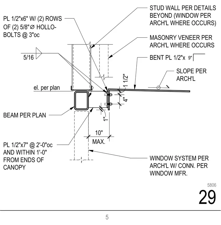
A structural canopy beam connects to a stud wall assembly with a half-inch by six-inch plate secured by two rows of two five-eighth-inch diameter Hollo-Bolts spaced at three inches on center. A half-inch by nine-inch bent plate extends outward at a slope defined per architectural drawings, supported by a half-inch by seven-inch plate spaced at two feet on center and within one foot from the ends of the canopy. A five-sixteenth-inch fillet weld connects the structural steel framing. The assembly interfaces with adjacent stud walls, window systems, and masonry veneer configured per architectural details.
BEAM PER PLAN 5/16 1 1/2" MAX. 10" BENT PL 1/2"x 9" 4" PL 1/2"x6" W/ (2) ROWS OF (2) 5/8" ⌀ HOLLO- BOLTS @ 3"oc PL 1/2"x7" @ 2'-0"oc AND WITHIN 1'-0" FROM ENDS OF CANOPY 1" el. per plan SLOPE PER ARCH'L STUD WALL PER DETAILS BEYOND (WINDOW PER ARCH'L WHERE OCCURS) WINDOW SYSTEM PER ARCH'L W/ CONN. PER WINDOW MFR. MASONRY VENEER PER ARCH'L WHERE OCCURS 5 29 5806
Members view this detail in full resolution, download the CAD files (SVG, PDF), and can adapt it in the built-in CAD editor — export DXF, DWG, or PDF.
Start membership