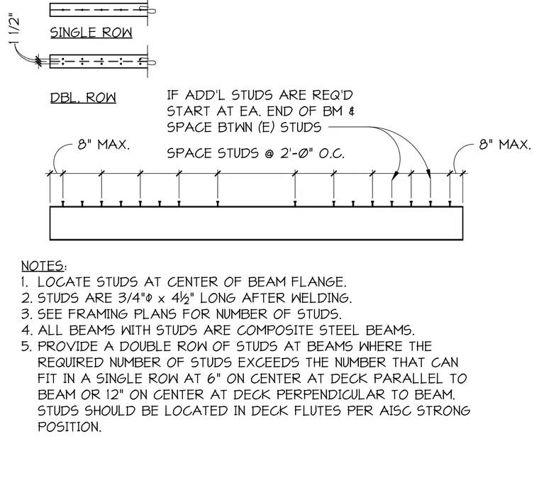
Shear studs are positioned along the center of the steel beam flange with dimensions specifying 3/4 inch diameter by 4 and 1/2 inches long after welding. Additional studs start at each end of the beam and space between existing studs at a maximum of 2 feet on center with an 8 inch maximum edge distance. A double row of studs is provided where the required number exceeds a single row capacity at 6 inches on center for decks parallel to the beam or 12 inches on center for decks perpendicular to the beam. Studs are located within deck flutes per American Institute of Steel Construction strong position.
IF ADD'L STUDS ARE REQ'D START AT EA. END OF BM & SPACE BTWN (E) STUDS SPACE STUDS @ 2'-0" O.C. 8" MAX. 8" MAX. DBL. ROW SINGLE ROW 1 1/2" 1 1/2" NOTES: 1. LOCATE STUDS AT CENTER OF BEAM FLANGE. 2. STUDS ARE 3/4"" x 4½" LONG AFTER WELDING. 3. SEE FRAMING PLANS FOR NUMBER OF STUDS. 4. ALL BEAMS WITH STUDS ARE COMPOSITE STEEL BEAMS. 5. PROVIDE A DOUBLE ROW OF STUDS AT BEAMS WHERE THE REQUIRED NUMBER OF STUDS EXCEEDS THE NUMBER THAT CAN FIT IN A SINGLE ROW AT 6" ON CENTER AT DECK PARALLEL TO BEAM OR 12" ON CENTER AT DECK PERPENDICULAR TO BEAM. STUDS SHOULD BE LOCATED IN DECK FLUTES PER AISC STRONG POSITION.
Members view this detail in full resolution, download the CAD files (SVG, PDF), and can adapt it in the built-in CAD editor — export DXF, DWG, or PDF.
Start membership