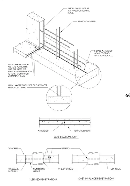
Waterstops are installed inside the outermost reinforcing steel at all footing-to-wall joints, wall pour joints, and slab pour joints to form a continuous waterproof barrier. Slab section joints incorporate continuous waterstops within the reinforced concrete slab. Pipe penetrations utilize either cast-in-place concrete coordination or sleeved penetrations filled with non-shrink grout and sealed with waterstops.
T.O. GRADE EL.: REF. DWGS BY OTHERS INSTALL WATERSTOP INSIDE OF OUTERMOST REINFORCING STEEL REINFORCING STEEL INSTALL WATERSTOP AT ALL FOOTING/ WALL JOINTS, R.A.D. INSTALL WATERSTOP AT ALL SLAB POUR JOINTS AND CONNECT WITH WALL JOINT INSTALLATION TO FORM CONTINUOUS WATERSTOP, R.A.D. NON-SHRINK GROUT INSTALL WATERSTOP AT ALL WALL POUR JOINTS, R.A.D. WATERSTOP REINFORCED SLAB SLAB SECTION JOINT CONCRETE CAST-IN-PLACE PENETRATION PIPE SLEEVE, BY OTHERS PIPE, BY OTHERS WATERSTOP SLEEVED PENETRATION CONCRETE
Members view this detail in full resolution, download the CAD files (SVG, PDF), and can adapt it in the built-in CAD editor — export DXF, DWG, or PDF.
Start membership