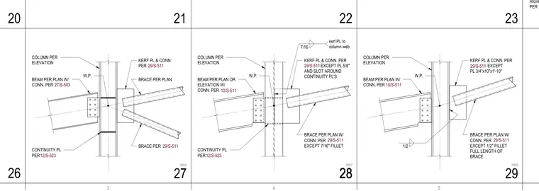
These structural details show braced frame and beam connections framing into a structural steel column. The assemblies feature work point configurations with kerf plates welded to the column web, slotted to clear continuity plates, and welded with specified fillet sizes such as 7/16 inch and 1/2 inch full length of brace. Beams connect to the column flange using bolted connections per plan, while chevron or diagonal braces tie into the kerf plates. Continuity plates are located per standard details to maintain column flange stability across the joint.
BEAM PER PLAN OR ELEVATION W/ CONN. PER 10/S-511 CONTINUITY PL PER 12/S-523 W.P. KERF PL & CONN. PER EXCEPT PL 5/8" AND SLOT AROUND CONTINUITY PL'S 29/S-511 BRACE PER PLAN W/ CONN. PER EXCEPT 7/16" FILLET COLUMN PER ELEVATION 7/16 kerf PL to column web 29/S-511 BEAM PER PLAN W/ CONN. PER 10/S-511 W.P. KERF PL & CONN. PER EXCEPT PL 3/4"x10"x1'-10" 29/S-511 BRACE PER PLAN W/ CONN. PER EXCEPT 1/2" FILLET FULL LENGTH OF BRACE COLUMN PER ELEVATION 29/S-511 1/2 HIGH LOAD CONN. PER BEAM PER PLAN W/ CONN. PER 27/S-503 CONTINUITY PL PER 12/S-523 W.P. KERF PL & CONN. PER 29/S-511 BRACE PER 29/S-511 BRACE PER PLAN COLUMN PER ELEVATION 20 21 22 23 26 28 28 5857 29 5862 27 5856
Members view this detail in full resolution, download the CAD files (SVG, PDF), and can adapt it in the built-in CAD editor — export DXF, DWG, or PDF.
Start membership