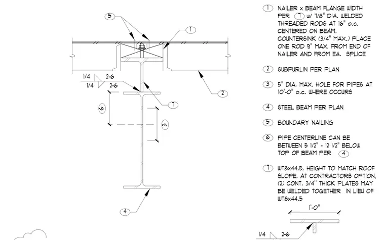
A wood nailer is secured to a structural steel beam via a WT8x44.5 shape whose height matches the roof slope, or optionally two continuous three-quarter-inch thick plates welded together. The wood nailer is fastened with seven-eighths-inch diameter welded threaded rods spaced at sixteen inches on center, centered on the beam with a maximum three-quarter-inch countersink. Place one rod a maximum of nine inches from the end of the nailer and from each splice. Subpurlins span per plan alongside boundary nailing, and the steel beam accommodates five-inch diameter maximum holes for pipes at ten-foot centers where required, with pipe centerlines positioned between five and one-half to twelve and one-half inches below the top of the beam.
1'-0" 4 2 1 5 6 6 TOP OF BEAM PER BETWEEN 5 1/2" - 12 1/2" BELOW PIPE CENTERLINE CAN BE 5 BOUNDARY NAILING 1 2 3 4 STEEL BEAM PER PLAN 5" DIA. MAX. HOLE FOR PIPES AT 10'-0" o.c. WHERE OCCURS SUBPURLIN PER PLAN 7 NAILER x BEAM FLANGE WIDTH PER w/ 7/8" DIA. WELDED THREADED RODS AT 16" o.c. CENTERED ON BEAM. COUNTERSINK (3/4" MAX.) PLACE ONE ROD 9" MAX. FROM END OF NAILER AND FROM EA. SPLICE 7 WT8x44.5. HEIGHT TO MATCH ROOF SLOPE. AT CONTRACTORS OPTION, (2) CONT. 3/4'' THICK PLATES MAY BE WELDED TOGETHER IN LIEU OF WT8x44.5 7 2-6 1/4 4 3 2-6 1/4 2-6 1/4
Members view this detail in full resolution, download the CAD files (SVG, PDF), and can adapt it in the built-in CAD editor — export DXF, DWG, or PDF.
Start membership