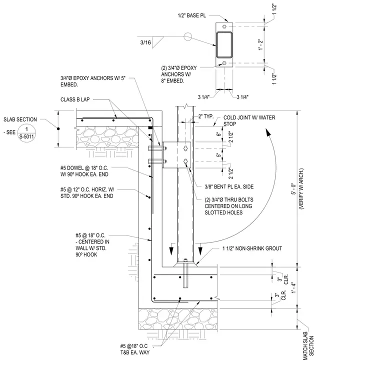
An elevator pit wall and guide rail support assembly comprises a concrete pit wall reinforced with number five dowels at eighteen inches on center with ninety-degree hooks at each end, alongside horizontal number five rebars at twelve inches on center with standard ninety-degree hooks. A cold joint with a water stop is incorporated into the wall assembly. The steel guide rail attaches to the concrete wall via a three-eighths-inch bent plate on each side, secured with two three-quarters-inch diameter through bolts centered on long slotted holes, and anchored back to the concrete with two three-quarters-inch diameter epoxy anchors featuring an eight-inch embedment. The vertical guide rail rests on a one-half-inch base plate over one and one-half inches of non-shrink grout, anchored to the foundation slab with a three-quarters-inch diameter epoxy anchor with five inches of embedment.
SECTION MATCH SLAB 1' - 4" (VERIFY W/ ARCH.) 5' - 0" CLR. 3" CLR. 3" 1/2" BASE PL 3/16 (2) 3/4"Ø EPOXY ANCHORS W/ 8" EMBED. CLASS B LAP COLD JOINT W/ WATER STOP #5 DOWEL @ 18" O.C. W/ 90º HOOK EA. END #5 @ 12" O.C. HORIZ. W/ STD. 90º HOOK EA. END #5 @ 18" O.C. - CENTERED IN WALL W/ STD. 90º HOOK #5 @18" O.C T&B EA. WAY 1 1/2" NON-SHRINK GROUT . 1 1/2" 1' - 2" 1 1/2" 3 1/4" 3 1/4" SLAB SECTION - SEE (2) 3/4"Ø THRU BOLTS CENTERED ON LONG SLOTTED HOLES 6" 2 1/2" 5" 2 1/2" 3/4"Ø EPOXY ANCHORS W/ 5" EMBED. 2" TYP. 3/8" BENT PL EA. SIDE 1 S-5011
Members view this detail in full resolution, download the CAD files (SVG, PDF), and can adapt it in the built-in CAD editor — export DXF, DWG, or PDF.
Start membership