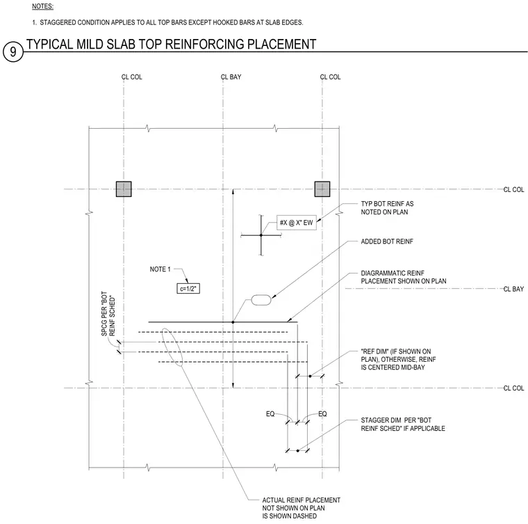
Placement conventions for mild steel top reinforcement in concrete slabs relative to column centerlines and bay lines. Typical bottom reinforcement as noted on plan with specified bar sizes and spacing in each way, alongside added bottom reinforcement and diagrammatic reinforcement placement. Actual reinforcement placement not explicitly shown on plan is represented by dashed lines. Staggered conditions apply to all top bars except hooked bars at slab edges, with stagger dimensions governed by the bottom reinforcing schedule. Reinforcement is centered mid-bay unless a reference dimension is provided on plan.
NOTES: 1. STAGGERED CONDITION APPLIES TO ALL TOP BARS EXCEPT HOOKED BARS AT SLAB EDGES. STAGGER DIM PER "BOT REINF SCHED" IF APPLICABLE DIAGRAMMATIC REINF PLACEMENT SHOWN ON PLAN NOTE 1 ADDED BOT REINF TYP BOT REINF AS NOTED ON PLAN #X @ X" EW ACTUAL REINF PLACEMENT NOT SHOWN ON PLAN IS SHOWN DASHED CL BAY CL COL CL COL CL BAY CL COL "REF DIM" (IF SHOWN ON PLAN), OTHERWISE, REINF IS CENTERED MID-BAY c=1/2" 24" EQ 12" EQ 30" CL COL SPCG PER "BOT REINF SCHED" 9 TYPICAL MILD SLAB TOP REINFORCING PLACEMENT
Members view this detail in full resolution, download the CAD files (SVG, PDF), and can adapt it in the built-in CAD editor — export DXF, DWG, or PDF.
Start membership